Subterranean excavation demands mechanical precision, structural reliability, and systematic efficiency. Over several decades, the transition from manual, hand-held pneumatic drilling to highly mechanized excavation methods has reshaped underground mining and civil tunneling. Modern development cycles rely heavily on specialized mechanized rigs to execute rapid, accurate blast hole patterns. Underground heavy equipment developer Aivyter focuses on engineering robust systems capable of enduring these harsh underground environments. At the core of high-speed tunneling and mining drift development are drill jumbos, which are sophisticated electro-hydraulic platforms configured to drill blast holes, bolting holes, and grout holes with repeatable accuracy.
Understanding the operational capabilities of these machines requires a deep look into their mechanical subsystems, hydraulic architectures, and interaction with varying geological formations. Selecting the right rig configuration directly determines heading advance rates, structural stability, and downstream processing efficiency.
Mechanical Architecture and Drilling Kinematics
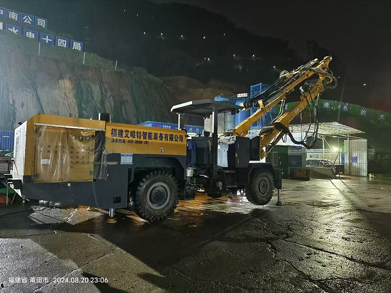
A mechanized rock drilling rig is a complex integration of structural steel, hydraulic power units, electrical control systems, and precision drilling instruments. To appreciate how these systems perform under load, we must analyze the key components that define their operation.
The Hydraulic Drifter
Often referred to as the rock drill, the hydraulic drifter is the component that converts hydraulic energy into mechanical impact and rotational force. It operates on a rotary-percussive principle. Inside the drifter, a piston moves rapidly back and forth, striking the shank adapter. This action transmits a compressive shockwave down the drill string to the button bit, fracturing the rock face. Simultaneously, a hydraulic motor drives a gear system to rotate the drill string, ensuring the bit buttons strike a fresh rock surface with each impact. Key parameters determining drifter performance include:
- Impact Frequency: Typically ranging from 40 to 80 Hz, determining how many times the piston strikes the shank per second.
- Impact Energy: The kinetic energy per blow, measured in Joules, tailored to overcome the compressive strength of specific rock types.
- Rotation Torque: The twisting force required to turn the bit under high feed force, preventing stalling in fractured or clay-rich formations.
Feed Beams and Boom Positioning Systems
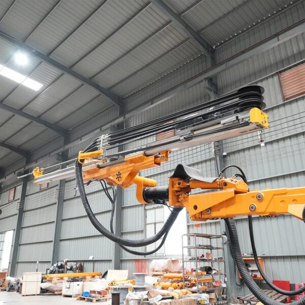
The feed beam guides the rock drill as it advances into the rock and retracts after completing a hole. Usually constructed from high-tensile alloy steel or lightweight aluminum profiles, the feed must resist bending forces and vibrations. It utilizes a hydraulic cylinder or a heavy-duty chain drive driven by a hydraulic motor to maintain constant pressure, or feed force, on the bit.
The booms support these feed beams, offering multi-directional positioning. Modern designs feature automatic parallel holding, allowing the feed to maintain its alignment relative to the tunnel axis as the boom moves from hole to hole. This mechanical alignment minimizes human error and preserves the geometrical integrity of the designed blast pattern.
Carrier Configurations
Carriers provide the mobility platform for the entire rig. They are categorized into wheel-mounted articulated chassis and tracked assemblies. Four-wheel-drive articulated carriers offer fast travel speeds between faces, making them suitable for mines with active headings separated by significant distances. Tracked carriers are preferred in steep declines, soft underfoot conditions, or highly restricted spaces where traction is paramount.
Application Profiles: Tunneling versus Underground Mining
While the primary drilling mechanism remains consistent, the operational profiles of drill jumbos diverge significantly depending on whether they are deployed in civil tunneling or underground production mining.
In civil tunneling, projects often require wide, continuous profiles such as transport tunnels, water diversion channels, or cavern excavations. These excavations utilize large-radius, multi-boom rigs capable of covering faces exceeding 100 square meters. The priority in civil tunneling is maintaining strict profile control to prevent overbreak—where excess rock is blasted beyond the planned design—and underbreak, which requires costly secondary drilling and scaling. Accurate positioning systems on multi-boom rigs allow engineers to maintain tight tolerances, ensuring smooth tunnel arches that conform to final lining specifications.
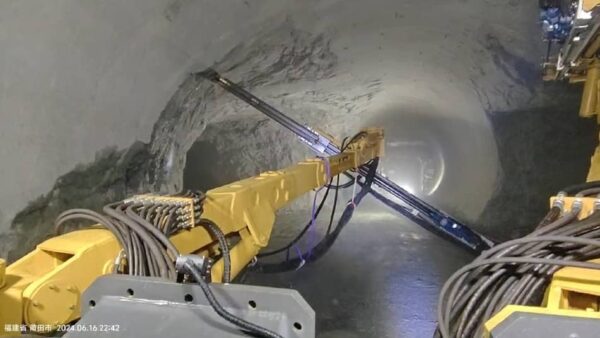
Underground mining, by contrast, frequently operates in narrow drifts, ramps, and sublevels. Rigs designed for these spaces must prioritize compact transport dimensions and high maneuverability. The drift dimensions are kept as small as economically viable to minimize waste rock dilution. Mining rigs require rapid setup times, agile boom movements, and the capacity to negotiate tight turning radii. Additionally, production drifts may experience rapid changes in geological stability, requiring the same machine to pivot between face drilling and installing localized ground support, such as split-sets or swellex bolts.
Mitigating Geological Complexities and Alignment Deviation
Underground excavation is rarely uniform. Rigs must continuously adapt to shifting geological formations, fractured rock zones, and unexpected water inflows. Successfully navigating these conditions relies on the coordination of control systems and mechanical robustness.
When drilling into highly fractured or blocky ground, the drill string is susceptible to jamming. If a block of rock shifts and pinches the rotating drill steel, the rotation torque rises sharply while penetration rates drop. Advanced hydraulic control circuits mitigate this by incorporating anti-jamming mechanisms. When the system detects a spike in rotation pressure, it automatically reduces feed pressure and reverses the feed direction. This action backs the drill bit off the bottom of the hole, allowing flushing water to clear the loose debris before resuming forward penetration.
Hole deviation is another persistent challenge in underground blast hole drilling. It occurs when a drill bit strikes a joint plane or a boundary between rocks of different hardness at an angle, causing the drill string to bend and drift off-course. This deviation results in uneven blast energy distribution, poor fragmentation, and bootlegs—unexploded bottom sections of blast holes. To counter this, heavy-duty guide sleeves and rigid feed designs are utilized to stabilize the initial collar phase of drilling. Furthermore, operators must carefully balance feed force and impact power; applying excessive feed force in hard rock can cause the drill rod to flex, compounding deviation issues.
Control Architectures and Operational Monitoring
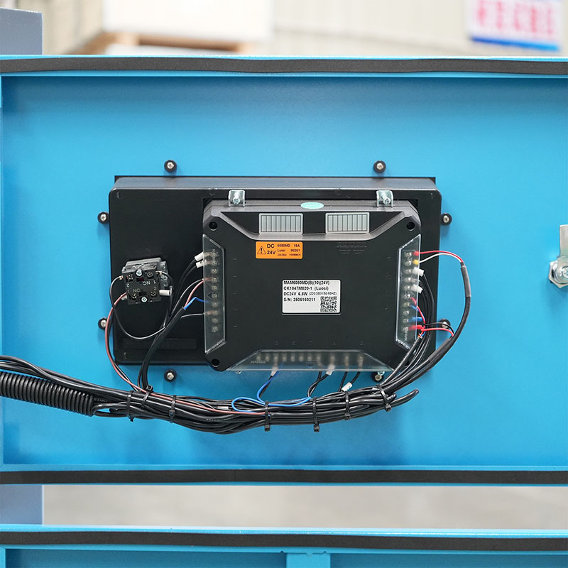
The transition from manual direct-acting hydraulic valves to digital control networks has improved machine reliability and structural longevity. Modern rigs utilize Controller Area Network (CAN-bus) architectures to manage the interactions between the operator’s inputs, the diesel engine or electric motor, and the hydraulic pumps.
These electronic control systems facilitate real-time monitoring of key operational parameters. By tracking variables such as percussion pressure, feed speed, rotation torque, and water flushing flow rates, the onboard computer can make micro-adjustments to the drilling cycle. For instance, if flushing water pressure drops below a safe threshold, the system immediately suspends percussion to prevent the bit from overheating and welding itself to the rock. This protective measure reduces component wear and extends the service life of expensive consumables like button bits and shank adapters.
Through robust engineering and field-tested component integration, manufacturers like Aivyter build machines designed to handle these automated cycles. Incorporating precise sensors on the boom joints allows the machine to calculate the exact spatial coordinates of the feed tip. This spatial data can be compared against pre-loaded drilling patterns, guiding the operator to each planned hole location with centimeter-level precision. This level of control reduces over-drilling, conserves explosives, and ensures uniform fragmentation during blasting.
Maintenance Frameworks for High-Utilization Excavation
The underground environment is highly abrasive, humid, and chemically aggressive. Achieving high machine availability requires structured, preventative maintenance protocols tailored to the unique stresses placed on drill jumbos.
Daily inspections must focus on the high-wear interfaces of the drilling system. The shank adapter, which receives tens of thousands of high-energy impacts every minute, must be inspected for micro-fracturing and wear on the splines. The slide pieces on the feed beam, which guide the drifter’s travel, require regular adjustment to eliminate play. Excessive play in the slide rails allows the drifter to vibrate laterally, leading to rapid wear of the feed components and increased drill string deviation.
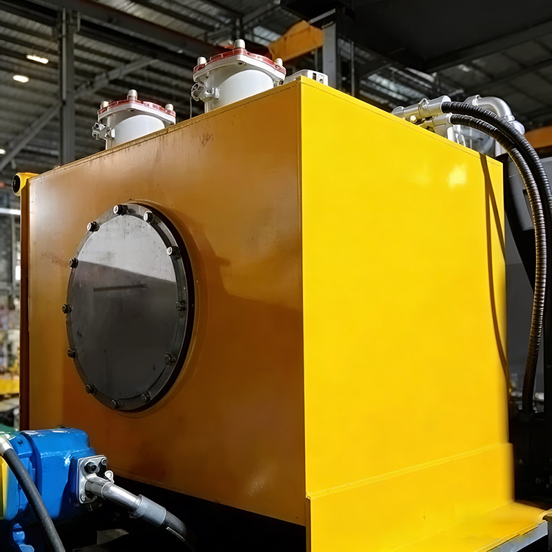
Hydraulic system cleanliness is another critical factor. Because hydraulic drifters operate at high pressures—often exceeding 200 bar—and high cycle frequencies, even minor particulate contamination can cause catastrophic component failure. The hydraulic oil must be regularly sampled and run through high-efficiency filtration loops. Additionally, the nitrogen-filled accumulators on the drifter, which absorb hydraulic pressure spikes and store energy for the impact stroke, must be checked weekly. A discharged accumulator leads to severe hydraulic line vibration, causing premature hose failures and structural fatigue on the boom assemblies.
Sourcing and Selecting the Right Rig Configuration
Selecting the optimal rig configuration requires a systematic evaluation of your project’s physical and operational constraints. There is no one-size-fits-all solution; every machine specification must align with the target excavation design.
Begin by mapping the minimum and maximum drift cross-sections of the mine or tunnel project. A rig with too small a coverage envelope will require multiple setups to complete a single face, while an oversized rig will struggle to navigate corners and may suffer boom clearance issues against the rock walls. Next, analyze the power infrastructure of the site. Most underground rigs operate on an electro-hydraulic principle, plugging into the mine’s electrical grid via a trailing cable during drilling, while using a diesel engine or battery pack solely for tramming between headings. Ensure the rig’s electric motor matches the site’s voltage, frequency, and available amperage.
Consider also the flushing requirements. Drilling in hard rock produces large volumes of fine cuttings that must be cleared from the hole to prevent the bit from grinding existing debris. This requires a stable supply of pressurized water or, in some dry mining operations, high-velocity compressed air. The rig’s onboard booster pumps must be capable of delivering the flow rates and pressures required to flush the deep holes drilled by high-performance drill jumbos.
Frequently Asked Questions (FAQ)
Q1: What are the main differences between single-boom and multi-boom configurations?
A1: Single-boom rigs are highly maneuverable and suited for small-profile drifts, narrow-vein mining, and localized utility drilling. Multi-boom rigs (typically featuring two or three booms, sometimes with an additional service platform) are designed for large civil tunnels or major mining haulages. They allow simultaneous drilling of multiple blast holes, drastically reducing the cycle time required to complete a large face pattern, though they require wider clearance to operate efficiently.
Q2: How does flushing medium selection affect drilling speed and tool wear?
A2: Water flushing is the standard for most underground operations as it suppresses silica dust and cools the drill bit. High water pressure clears cuttings efficiently, preventing re-drilling of particles and reducing abrasive wear on the bit inserts. Air flushing is used when water is scarce or when drilling in water-sensitive swelling ground; however, it requires robust dust-collection systems and can lead to higher thermal stress on the drill bit buttons due to less efficient cooling.
Q3: What causes rapid shank adapter wear, and how can it be prevented?
A3: Rapid wear or premature failure of the shank adapter is usually caused by insufficient feed force, misalignment between the feed and the hole, or poor lubrication. When feed force is too low, the drill string bounces, causing tensile stress waves that damage the threads and splines. Ensuring correct feed pressure settings, maintaining slide alignment, and verifying that the drifter’s automatic lubrication system is delivering the correct oil volume to the shank interface will prevent premature failure.
Q4: How does parallel boom holding maintain blast pattern accuracy?
A4: Parallel boom holding utilizes mechanical linkages or electro-hydraulic feedback sensors to keep the feed beam oriented at the exact same angle (parallel to the tunnel axis) as the boom is raised, lowered, or swung sideways. This prevents the blast holes from diverging or converging, which is critical for achieving an even pull-out of rock and maintaining a smooth tunnel profile after the blast.
Q5: How do operators adjust feed pressure relative to varying rock hardness?
A5: In hard, competent rock, higher feed pressure is required to keep the bit buttons in constant contact with the rock face, allowing the impact energy to transfer efficiently. In soft or fractured rock, feed pressure must be reduced to prevent the bit from plunging too fast, which can overload the rotation motor, cause drill string deviation, or jam the steel in the hole.
Discuss Your Subterranean Drilling Requirements
Industrial excavation projects require equipment that delivers reliable performance under demanding conditions. Selecting the correct machinery configuration involves balancing geological characteristics, spatial constraints, and energy infrastructure. The engineering team at Aivyter is available to analyze your specific tunnel dimensions, rock conditions, and operational parameters to recommend an optimized equipment configuration.
To request technical specifications, dimensional drawings, or a detailed quotation tailored to your upcoming project, please submit your inquiry and site requirements through our contact portal today.
about
Aivyter
We provides trusted air compressors and mining equipment, engineered for durability, efficiency, and demanding industrial applications.