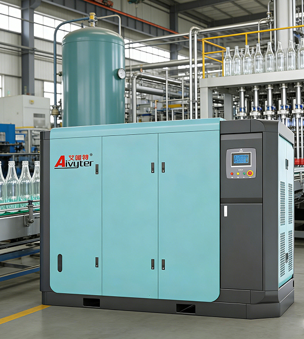

Compressed air serves as a primary utility in heavy industries, powering pneumatic machinery, automation systems, and material handling equipment. To maintain stable pressure levels and manage intermittent high demand, industrial compressed air systems require high-performance air receivers to act as temporary storage reservoirs. These pressure vessels perform functions far beyond simple storage, serving as pressure stabilizers, cooling units, and primary moisture separation systems.
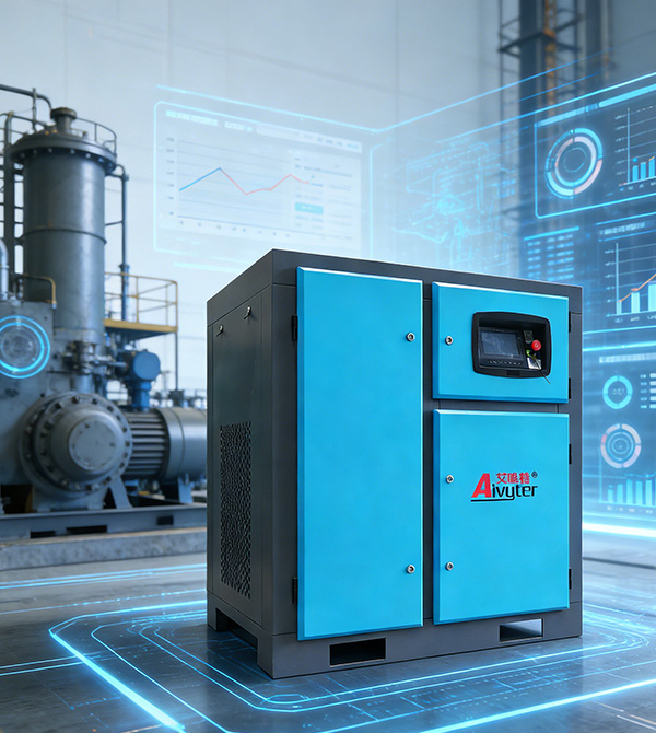
Industrial manufacturers such as Aivyter provide heavy-duty compression systems that rely on these storage vessels to balance air supply with fluctuating plant demands. Selecting the correct vessel capacity, placement, and configuration is a key engineering decision that impacts downstream air quality, compressor motor wear, and system reliability.
The Engineering Functions of Compressed Air Storage
In any industrial network, air demand is rarely constant. Fluctuations occur when high-flow pneumatic tools cycle on and off, or when bulk material handling systems require sudden bursts of air. Without adequate storage, the air compressor must immediately ramp up production, leading to rapid motor cycling and systemic pressure drops.
An air receiver mitigates these issues by acting as an energy dampener. By storing a volume of pressurized air, the vessel handles sudden load peaks without forcing the compressor to load or start. This storage capability reduces the frequency of motor start-stop cycles, extending the operating life of the compressor motor and drive assembly.
The vessel also functions as an effective heat exchanger. As hot, compressed air enters the receiver, it comes into contact with the cooler internal walls of the vessel. This temperature drop causes moisture vapor to condense into liquid water, which pools at the bottom of the tank. Removing this bulk condensate before the air enters downstream dryers and filtration units prevents premature element saturation and pipe corrosion.
Additionally, reciprocating compressors generate pressure pulsations that can propagate through downstream piping, causing vibration and measurement errors in flow sensors. The large volume of the storage tank acts as a pulsation dampener, smoothing out these pressure waves to ensure a steady, laminar flow of compressed air throughout the plant distribution network.
Wet vs. Dry Air Receivers: System Design and Layout
The positioning of storage vessels relative to filtration and drying equipment determines their classification as either wet or dry storage. Both configurations serve specific roles, and many complex industrial plants utilize a combination of both to protect downstream processes.
Wet Storage Configuration
A wet receiver is positioned directly downstream of the compressor, before any air dryer or filtration equipment. In this location, the vessel receives saturated air containing water vapor, oil mist, and particulate matter. The primary benefit of this arrangement is the maximizing of moisture separation.
- Moisture Pre-Separation: The expansion and cooling of air inside the vessel allows up to 70% of entrained water and oil to condense, protecting downstream desiccant or refrigerated dryers from liquid overloading.
- Dryer Capacity Preservation: By smoothing out flow surges, the wet vessel prevents high velocity spikes from passing through the dryer. This ensures that the air velocity remains within the dryer’s designed retention time, maintaining the specified dew point.
- Compressor Control Stability: Since the compressor senses pressure at the wet tank, the load/unload cycles are controlled based on total system volume, preventing rapid cycling.
Dry Storage Configuration
A dry receiver is installed downstream of the air dryers and filtration systems, storing clean, dry air. When designing the layout, integrating air receivers either before or after the drying unit changes how the system responds to sudden demands.
- Instantaneous Supply for Peak Demand: When a sudden demand spike occurs, the dry air is drawn directly from the dry tank, preventing wet or untreated air from bypassing the dryer during a surge.
- Reduced Dryer Load: Dry storage prevents dry air from flowing back into the wet side of the system, keeping the dryer operating at a constant, steady load.
- Secondary Buffer: In large manufacturing complexes with long piping runs, placing dry storage vessels near the point of use prevents localized pressure drops.
Integrating both wet and dry storage vessels creates a highly stable, energy-efficient compressed air network. The wet vessel manages the raw compressor discharge and removes bulk moisture, while the dry vessel provides clean air reserves close to sensitive manufacturing processes.
Engineering Sizing and Calculations for Industrial Air Vessels
Undersized storage vessels lead to frequent compressor loading and unloading, resulting in accelerated mechanical wear and fluctuating system pressure. Correctly sizing these units requires a systematic approach based on compressor capacity, system demand patterns, and allowable pressure variances.
The standard formula used by plant engineers to calculate the minimum storage volume is:
V = (t × (C – S) × Pa) / (P1 – P2)
Where the parameters are defined as:
- V: Receiver volume in cubic feet (or converted to liters).
- t: Time duration of the peak demand period in minutes.
- C: Peak air demand required by the system (Cubic Feet per Minute, CFM).
- S: Compressor capacity (CFM).
- Pa: Atmospheric pressure (typically 14.7 PSI absolute at sea level).
- P1: Maximum allowable receiver pressure (PSI gauge).
- P2: Minimum allowable operating pressure at the point of use (PSI gauge).
To put this formula into practice, consider a manufacturing plant where the compressor outputs 500 CFM at 100 PSIG. A pneumatic process cycles on for 1.5 minutes, requiring a peak flow of 800 CFM. The minimum pressure the process can tolerate is 85 PSIG.
Using the sizing formula, the calculation proceeds as follows:
- t = 1.5 minutes
- C – S = 800 CFM – 500 CFM = 300 CFM
- P1 – P2 = 100 PSIG – 85 PSIG = 15 PSI
- V = (1.5 × 300 × 14.7) / 15 = 441 cubic feet
Converting this value to gallons (since industrial vessels are typically rated in gallons) requires multiplying by 7.48. Thus, 441 cubic feet corresponds to approximately 3,300 gallons of storage. In this scenario, installing multiple smaller vessels or a single large tank is necessary to maintain pressure stability during the peak demand phase.
When selecting standard industrial configurations, a general rule of thumb for constant demand systems is to allocate 1 to 2 gallons of storage per CFM of compressor capacity. For systems utilizing variable speed drive (VSD) compressors, this ratio can be reduced, as the compressor adjusts its output dynamically. However, for fixed-speed systems with high peak demands, using standard sizing parameters recommended by Aivyter engineers ensures the system runs without excessive motor wear.
A properly calculated volume for air receivers prevents rapid cycling, maintaining a smooth pressure band and reducing mechanical stress across the entire distribution network.
Regulatory Compliance and Safety Engineering
Because they store pressurized gas, these vessels are classified as high-hazard pressure vessels under various international and national safety codes. Compliance with manufacturing standards is mandatory to prevent structural failures and maintain a safe working environment.
The ASME Boiler and Pressure Vessel Code
In North America and many international markets, pressure vessels must comply with Section VIII, Division 1 of the American Society of Mechanical Engineers (ASME) Boiler and Pressure Vessel Code. This standard regulates the design, materials, fabrication, inspection, and testing of vessels operating at internal pressures exceeding 15 PSI.
ASME-certified vessels feature a permanent metal nameplate indicating the Maximum Allowable Working Pressure (MAWP) at a designated temperature, along with a unique registration number from the National Board of Boiler and Pressure Vessel Inspectors. Using non-ASME certified tanks in industrial facilities is often a violation of local occupational safety laws and can invalidate commercial insurance policies.
European Pressure Equipment Directive (PED)
For installations within the European Economic Area, vessels must conform to the Pressure Equipment Directive (2014/68/EU). This directive classifies equipment based on its pressure-volume (PS-V) rating, requiring formal CE marking and conformity assessments by notified bodies.
Required Safety Accessories
An industrial air vessel must never be operated without functional, calibrated safety controls. The safety array consists of several key physical components:
- Safety Relief Valve (SRV): A spring-loaded mechanical valve set to open automatically if the internal pressure exceeds the vessel’s rated MAWP. The discharge capacity of the valve must be larger than the maximum output of all connected compressors combined.
- Pressure Gauge: A calibrated analog or digital indicator that displays the current internal pressure of the vessel, allowing operators to verify safe working conditions.
- Condensate Drain Valve: A manual, electronic timer-controlled, or float-activated drain valve installed at the lowest point of the vessel to discharge accumulated water and oil mixtures.
- Inspection Ports: Handholes or manways that allow safety inspectors to perform internal ultrasonic thickness testing and visual inspections for corrosion.
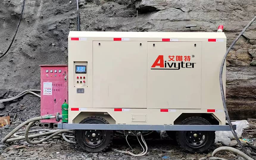
Operational Challenges in Mining, Construction, and Heavy Manufacturing
Heavy-duty industries rely on heavy-walled air receivers to withstand demanding conditions, but these harsh environments present unique operational challenges. In mining and construction, ambient dust, vibration, and extreme temperature swings put significant strain on pressure vessels.
A major challenge in these environments is internal and external corrosion. Wet air entering the receiver contains acidic combustion byproducts, ambient moisture, and particulate matter. Over time, this mixture creates an acidic condensate that corrodes the bare steel inside the vessel, thinning the walls and lowering the maximum safe pressure capacity. To counter this, heavy-duty industrial vessels feature internal epoxy coatings or are constructed from corrosion-resistant alloys.
Another operational issue is condensate management. If a drain valve becomes clogged by mining dust or heavy oil grease, water accumulates inside the tank. This reduces the effective storage volume, leading to immediate pressure drops downstream and water carryover into the air lines. Implementing high-capacity systems from Aivyter helps stabilize these parameters by combining robust zero-loss electronic drains with high-efficiency separation systems designed for high-dust environments.
Industrial System Engineering and Custom Solutions
Selecting the correct air storage equipment requires evaluating your specific application demands, environmental conditions, and layout restrictions. A mismatch in vessel sizing or filtration integration can lead to pressure drops, premature equipment failure, and production delays.
Our engineering team works closely with B2B procurement managers, plant operators, and engineering contractors to design configured compressed air systems that match your exact performance requirements. Whether you require custom ASME-certified vessels, high-durability internal coatings for corrosive environments, or complete compressor station layouts, we can provide the necessary engineering expertise.
To discuss your plant parameters, obtain detailed mechanical drawings, or request a quotation for industrial air receivers, please submit your specifications to our project division. Contact our engineering department for custom specifications on industrial equipment designed for your specific application.
Frequently Asked Questions
Q1: What is the main difference between a vertical and a horizontal air receiver?
A1: Vertical models occupy less floor space and are preferred in compact facilities, whereas horizontal models are often paired directly underneath compressor packages for low-clearance areas. Both serve the same storage function, but vertical models allow for more efficient gravity-based condensate separation due to their tall, vertical design.
Q2: How often should an air receiver be drained of condensate?
A2: Draining must occur regularly, often several times daily, or continuously via automatic electronic or zero-loss drains to prevent liquid carryover and internal corrosion. Manual draining is suitable for small operations but is often neglected in larger, automated production environments, making automatic drain valves a necessity.
Q3: What safety relief valve settings are required for an air receiver?
A3: The safety relief valve must be set at or below the Maximum Allowable Working Pressure (MAWP) stamped on the vessel’s ASME or PED nameplate. The valve’s flow capacity must be sized to discharge the maximum possible flow rate of the connected compressor system to prevent over-pressurization.
Q4: Can an air receiver be installed outdoors?
A4: Yes, provided it is equipped with appropriate external coatings, freeze protection for the condensate drain, and a pressure relief valve rated for outdoor temperatures. Outdoor installations must also account for wind loads and seismic design requirements specified by local building codes.
Q5: Why is a wet air receiver recommended before a desiccant dryer?
A5: It removes a significant percentage of liquid water and bulk oil, protecting the desiccant material from water flooding and premature degradation. This pre-separation reduces the thermal load on the dryer, allowing it to work more efficiently and extend the service life of the desiccant beads.
about
Aivyter
We provides trusted air compressors and mining equipment, engineered for durability, efficiency, and demanding industrial applications.