Subsurface excavation in mining and civil infrastructure requires highly mechanized solutions to maintain structural stability, ensure operator safety, and meet demanding project timelines. For decades, the transition from manual drilling methods to mechanized systems has redefined how rock is penetrated and broken. At the center of this mechanical evolution is the drill jumbo, a specialized piece of heavy machinery designed to drill blast holes, rock bolt holes, and grout holes with high precision. Understanding the mechanical complexities, operational parameters, and structural design of these machines is necessary for any engineering team planning complex tunneling or mining operations.
Modern excavation projects demand equipment that can withstand high-stress environments while maintaining continuous operation. Heavy machinery manufacturers, such as Aivyter, focus on developing robust drilling platforms that integrate advanced hydraulics and sturdy structural frames to meet these rigorous demands. This comprehensive analysis examines the core engineering systems, geological considerations, and operational methodologies that govern the use of mechanized drilling systems in modern heavy industry.
Core Engineering Systems of a Modern Drill Jumbo
A mechanized drilling rig is not a single tool, but rather an integration of several highly coordinated mechanical, hydraulic, and electrical systems. Each subsystem plays a distinct role in transferring energy from the power source to the rock face.
The Hydraulic Rock Drill (Drifter)
The drifter is the mechanical heart of the machine, responsible for converting hydraulic energy into high-frequency percussive impact and rotational force. This rotary-percussive action is necessary for fracturing hard rock formations. The hydraulic piston within the drifter strikes the shank adapter at frequencies typically ranging from 40 to 60 Hz. This impact generates a stress wave that travels down the drill steel to the button bit, crushing the rock at the bottom of the hole. Simultaneously, a hydraulic rotation motor provides the torque necessary to rotate the drill string, ensuring that the carbide buttons on the bit strike fresh rock with every blow. To prevent dust accumulation and overheating of the bit, flushing medium—usually water or a water-air mixture—is pumped through the center of the drill steel to flush out rock cuttings.
Hydraulic Boom Positioning Systems
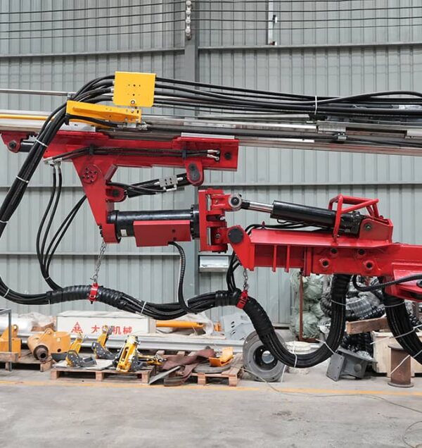
Precision in hole placement and alignment is governed by the boom system. Modern rigs feature double-tripod or telescopic booms that provide wide coverage areas. These booms are engineered with automatic parallel holding mechanisms, which ensure that the feed beam remains parallel to the pre-set alignment of the tunnel or drift, regardless of how the boom is positioned. This automatic parallelism is vital for drilling straight, parallel blast holes, which directly affects the efficiency of the subsequent blast. The coverage area of a single boom can range from 10 to over 100 square meters, depending on the machine size and configuration.
Propulsion and Feed Mechanisms
The feed system is the structural channel that guides the rock drill during the drilling process. Typically constructed from heavy-duty aluminum alloy or structural steel profiles, the feed beam utilizes a hydraulic cylinder or a heavy chain drive to apply feed force (pulldown pressure) to the drifter. Correct feed force is necessary; insufficient force leads to loose threads and premature wear on the drill steel couplings, while excessive force can cause hole deviation or jam the drill string. Slide pieces made of low-friction synthetic materials are positioned between the drifter and the feed beam to facilitate smooth linear movement and minimize mechanical wear.
Carrier and Power Configurations
The carrier serves as the mobile foundation for the entire assembly. Depending on the operational environment, carriers are categorized into two primary types:
- Rubber-Tired Articulated Carriers: Highly maneuverable units designed for rapid relocation between different headings in underground mines. These carriers feature four-wheel drive and heavy-duty axles to navigate steep declines and rough underfoot conditions.
- Crawler-Mounted Carriers: Selected for highly rugged, unstable terrains, particularly in civil tunneling projects where wet floor conditions or steep inclines restrict wheeled mobility.
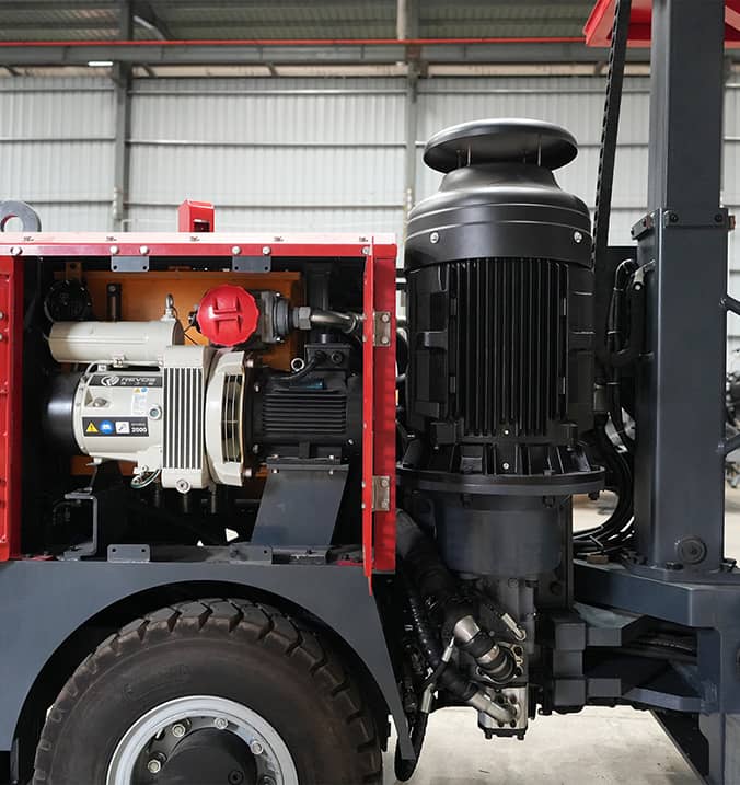
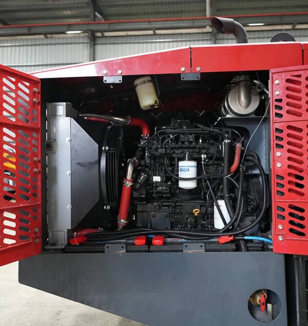
Power configurations generally involve a dual-system setup. A diesel engine is utilized for tramming the carrier between locations, while an electric motor is connected to an external power grid via a cable reel to run the main hydraulic pumps during the actual drilling phase. This approach maintains underground air quality by eliminating diesel emissions during stationary operations.
Engineering Solutions to Common Geological and Operational Challenges
Every underground project presents unique geological variations that can disrupt excavation schedules if not properly managed. Applying a standard drill jumbo to variable rock conditions requires a thorough understanding of rock mechanics and structural engineering.
Managing Structural Overbreak and Underbreak
In tunneling, overbreak (excavating beyond the design profile) and underbreak (failing to excavate up to the design profile) are persistent operational challenges. Overbreak results in excess material removal and increases the volume of shotcrete or concrete lining required to secure the tunnel. Underbreak, on the other hand, requires tedious mechanical scaling or secondary blasting, which halts the excavation cycle. To mitigate these structural deviations, precise positioning systems are integrated into the booms. Heavy-duty equipment from Aivyter is engineered with robust alignment guides that resist structural flexing during operation, helping operators maintain strict adherence to the planned blast hole pattern.
Mitigating Rock Mass Fractures and Void Intersections
When drilling through highly fractured rock or encountering sudden geological voids, there is a possibility of the drill bit binding or becoming completely trapped. To prevent this, modern hydraulic circuits feature anti-jamming mechanisms. When the rotation pressure exceeds a pre-determined threshold—indicating that the bit is encountering resistance or squeezing ground—the system automatically reverses the feed direction while maintaining rotation. This automatic adjustment clears the path and preserves the integrity of the drill string, preventing costly delays associated with lost tooling.
Water Ingress and Soft Ground Drilling
Encountering high-pressure water inflows or highly weathered, soft rock zones requires rapid adaptation. In soft ground, percussive energy must be dialed back to prevent the bit from plunging too quickly, which can cause hole collapse. When high-pressure water is detected during probe drilling, the machine can be configured to install grout holes quickly. Cementitious or chemical grout is injected through these holes to seal the surrounding rock mass before main excavation resumes.
Industrial Application Scenarios: Tunneling vs. Underground Mining
While the fundamental mechanism of rock penetration remains the same, the operational demands of civil tunneling differ significantly from those of underground mining. These differences dictate the configuration of the drilling equipment.
Civil Infrastructure Tunneling
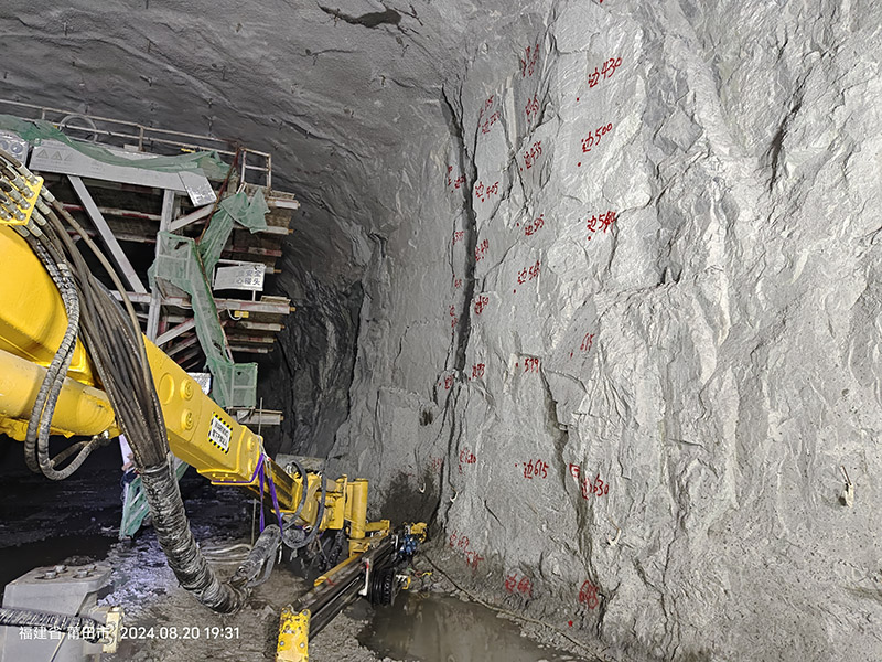
Civil projects, such as railway, highway, and hydropower tunnels, typically demand large-cross-section excavations. These tunnels require wide, uniform spans that must accommodate permanent transport infrastructure. Consequently, multi-boom rigs are common in these operations. A three-boom or four-boom drill jumbo, often equipped with an integrated service platform, allows multiple operators to drill the blast pattern simultaneously, reducing cycle times. The focus here is on high positioning accuracy and maintaining a smooth contour to ensure long-term structural integrity.
Underground Mine Development and Production
Underground mining operations prioritize flexibility and rapid adaptation to changing geological veins. Main haulage drifts, crosscuts, and ramps must be developed quickly to access ore bodies. In these environments, space is often constrained. Mining operators favor compact, highly agile single-boom or double-boom units. These machines must be able to navigate tight turning radii, negotiate steep ramp grades, and quickly reposition between multiple active faces across different levels of the mine. Speed of relocation and mechanical reliability are the primary parameters for mine development machinery.
| Operational Parameter | Civil Infrastructure Tunneling | Underground Mine Development |
|---|---|---|
| Typical Cross-Section Size | Medium to Large (40 m² to over 120 m²) | Small to Medium (12 m² to 35 m²) |
| Boom Configuration | Multi-boom (2 to 4 booms with service basket) | Single or Double-boom (highly compact design) |
| Profile Accuracy Requirement | Extremely high to minimize concrete lining use | Moderate, focused on rapid advance rates |
| Equipment Mobility | Semi-stationary, prolonged operation at one face | High mobility, frequent travel between levels |
Key Performance Parameters for Equipment Selection
Procuring a drill jumbo is a capital decision that requires careful matching of machine specifications with the planned excavation methodology. Several engineering variables must be evaluated during the selection process.
- Uniaxial Compressive Strength (UCS) of the Rock: Extremely hard rock (above 200 MPa) requires high-frequency drifters with robust percussive force, whereas softer rock (below 80 MPa) may require higher rotation speeds and lower impact energy to avoid bit plugging.
- Boom Reach and Coverage: The maximum width and height of the tunnel profile must fall comfortably within the operating envelope of the booms to avoid leaving unexcavated sections near the floor or crown.
- Feed Length and Hole Depth: The length of the feed beam determines the depth of each round. Selecting the correct feed length is a balance between the desired advance rate per round and the space available at the face for the machine to maneuver.
- Electrical System Compatibility: Underground mines operate on various voltage levels (typically 380V, 660V, or 1000V at 50Hz/60Hz). The machine’s electrical package must align with the site’s infrastructure to prevent power supply issues.
By consulting with engineering experts at Aivyter, procurement teams can select custom configurations that match the specific hydraulic capacities, boom dimensions, and drifter specifications required for their local geology.
Preventive Maintenance Protocols for Underground Excavation Drills
The harsh underground environment—characterized by corrosive water, abrasive dust, and vibration—imposes severe wear on mechanical components. Implementing a systematic preventive maintenance schedule is necessary to ensure long equipment life and prevent unscheduled stoppages.
First, hydraulic oil cleanliness must be monitored closely. Particulate contamination can quickly degrade high-precision hydraulic valves within the drifter and control blocks. Utilizing high-efficiency filtration systems and conducting regular oil analysis helps identify internal wear before a component failure occurs. Second, the shank adapter and drill steel threads require continuous lubrication. This is typically achieved via an onboard pneumatic lubrication system that delivers a constant mist of oil to the moving parts. Third, slide pieces on the feed beam must be inspected and adjusted regularly; excessive play in the feed slide leads to misalignment of the drill string, causing uneven bit wear and potential hole deviation.
Inquiries and Customized Engineering Solutions
Selecting the appropriate underground drilling machinery involves analyzing complex variables, from geological conditions to hydraulic flow requirements. Standard configurations may not always deliver the performance required for specialized tunneling or mine development projects.
We invite engineering leads, project managers, and procurement professionals to submit an inquiry with detailed project specifications. Our engineering team can assist in matching the appropriate drill jumbo configuration, drifter power, and boom reach to your specific operational parameters. Please contact us to discuss your underground excavation requirements and receive a comprehensive proposal tailored to your engineering needs.
Frequently Asked Questions (FAQ)
Q1: What is the primary difference between a single-boom and a multi-boom drill jumbo?
A1: The primary difference lies in coverage area and excavation speed. A single-boom machine is compact and maneuverable, suited for narrow-vein mining and small development drifts. Multi-boom machines feature two, three, or four booms, enabling them to cover large cross-sections in civil tunneling. This allows multiple holes to be drilled simultaneously, which significantly reduces the cycle time for wide faces.
Q2: How does rock hardness influence the choice of hydraulic drifter?
A2: Rock hardness, measured by Uniaxial Compressive Strength (UCS), dictates the required impact frequency and torque. Harder rock formations require a drifter with higher percussive energy and frequency to fracture the rock matrix effectively. Softer rock formations require less percussive impact but may need higher rotational speeds to evacuate loose material quickly and prevent the drill bit from binding.
Q3: What measures prevent drill steel deviation during deep-hole drilling?
A3: Drill steel deviation is minimized by maintaining proper alignment of the feed beam, ensuring slide pieces are adjusted to prevent lateral play, and using guide devices on the feed structure. Additionally, hydraulic systems that automatically adjust feed force based on real-time rotation pressure prevent excessive force from flexing the drill steel in hard or uneven rock formations.
Q4: Can a standard drill jumbo be used for both tunneling and production mining?
A4: Yes, although the machine configuration may need adjustments. For tunnel development, the focus is on drilling horizontal blast holes parallel to the tunnel axis. For production mining, particularly in methods like sublevel stoping, the boom and feed must be capable of drilling angled or vertical holes. Some versatile configurations allow the feed beam to rotate through a wider range of angles to accommodate both applications.
Q5: Why is water flushing preferred over air flushing in underground excavations?
A5: Water flushing is preferred in underground operations primarily for dust suppression, which is necessary to maintain clean air for operators. Water also provides superior cooling for the drill bit carbide buttons under high-friction conditions. Air flushing is generally reserved for surface applications or specific underground environments where water contact could cause structural swelling of clay-rich host rock.
about
Aivyter
We provides trusted air compressors and mining equipment, engineered for durability, efficiency, and demanding industrial applications.