")
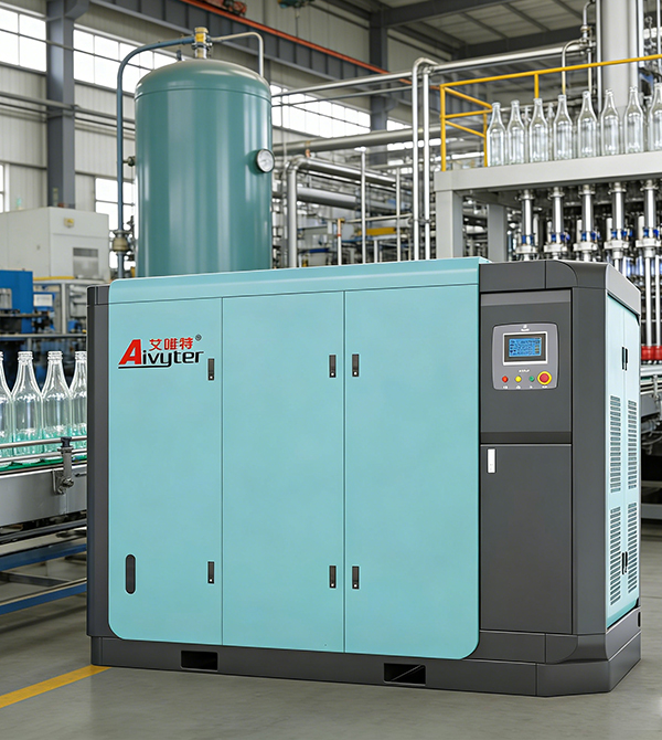
In deep mining operations, large-diameter tunnel boring, and offshore construction, the high pressure screw air compressor has become a mandatory utility instead of a luxury. Unlike general-purpose rotary screw units that fade above 15 bar, purpose-built high-pressure systems routinely deliver 30 to 45 bar at sustainable flow rates exceeding 50 m³/min. For project engineers and maintenance managers, understanding the internal architecture, failure modes, and site-specific performance tuning of these machines directly translates to reduced downtime and lower kilowatt-hour per cubic meter costs. This guide examines the technical foundation of high pressure screw air compressor technology, references real-world installations in abrasive environments, and provides a structured selection framework.
Core Design Differences of a High Pressure Screw Air Compressor
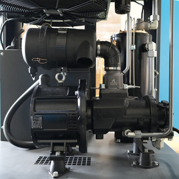
Standard industrial screw compressors operate at pressure ratios of 8:1 to 10:1 per stage. To reach discharge pressures of 30 bar (absolute) from atmospheric inlet, the required pressure ratio exceeds 30:1. A single-stage screw cannot achieve this without extreme internal leakage and bearing overload. Consequently, genuine high pressure screw air compressor packages adopt a two-stage compression layout with inter-stage oil cooling and moisture separation.
Two-Stage Compression Architecture
In a typical two-stage high pressure screw air compressor, the low-pressure (LP) rotor set compresses inlet air to an intermediate level of 8–12 bar. The air then passes through an inter-stage cooler, reducing its temperature by 50–70°C, and enters a moisture separator to remove condensed water. The second high-pressure (HP) rotor stage boosts the pressure to the final setpoint (30–45 bar). This staged approach lowers the pressure ratio per stage to approximately 3.5:1 for LP and 3.8:1 for HP, preserving volumetric efficiency above 82% at full load. Field data from Aivyter installations show a 19% improvement in specific power (kW/m³/min) compared to single-stage screw units modified for high-pressure duty.
Screw Rotor Profiles and Surface Treatments
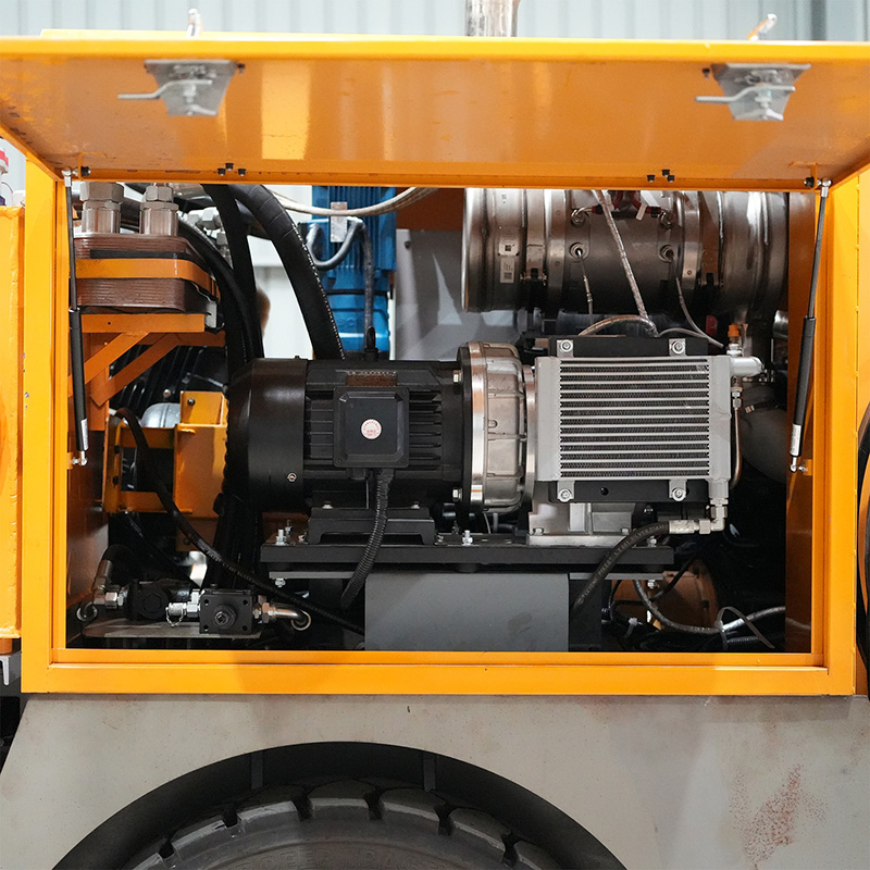
High-pressure service demands rotor geometries that minimize blow-hole area and internal leakage. Modern asymmetric profiles (e.g., 4+6 lobe combination with optimized sealing line) are standard. However, for pressures above 35 bar, rotor materials shift from ductile iron to case-hardened alloy steel (e.g., 20MnCr5) with a nitride diffusion layer of 0.3–0.5 mm. Surface hardness reaches 60–64 HRC, resisting micropitting from high-frequency pressure pulsations. Aivyter’s SGP-M series implements fifth-generation rotors with <0.02 mm profile error, verified by coordinate measuring machine inspection.
High-Pressure Oil Separation and Seal Systems
Oil carryover directly affects downstream air tools, instruments, and catalyst beds. In a high pressure screw air compressor, the oil separator vessel must withstand 45 bar hydraulic test pressure. Three-stage separation is typical: primary impingement, secondary coalescing filter (≤0.1 micron rating), and a scavenge line with orifice return. For shaft sealing, tandem mechanical seals with a buffer fluid (or pressurized barrier air) are mandatory. Some packages integrate a labyrinth seal with a pressure-break vortex, reducing seal leakage to <10 Nm³/h at 40 bar.
Field Application Analysis: Mining, Tunneling, and Energy Sectors
The high pressure screw air compressor proves its value in continuous, high-duty-cycle operations where reciprocating compressors show fatigue failures within 4000 hours.
Reverse Circulation (RC) and Deep-Hole Drilling
RC drilling for mineral exploration requires 30–35 bar air at 25–40 m³/min to lift cuttings through dual-wall drill rods. A single RC rig operating two 10-hour shifts consumes approximately 1500 m³ of compressed air per day. Two-stage screw compressors maintain stable discharge temperature (±4°C) across varying ambient conditions, preventing condensation inside the rod string. In Western Australian iron ore sites, conversion from four-cylinder piston units to screw-based systems reduced daily fuel consumption by 220 liters per rig and eliminated weekly valve service downtime.
Tunnel Boring Machine (TBM) Air Support
In soft-ground tunneling, compressed air is injected into the excavation chamber to balance groundwater pressure. The required pressure ranges from 2 to 5 bar, but the supply system must cope with rapid load changes when the TBM advances. A high pressure screw air compressor located at the tunnel portal (operating at 30 bar) feeds an air receiver bank and a pressure-reducing station. This configuration delivers instantaneous flow response without pressure spikes. Projects such as the Istanbul Grand Airport tunnel system employed three screw compressors in parallel to maintain 99.3% air availability over 28 months of continuous boring.
Offshore and Onshore Gas Lift / Instrument Air Boosting
On production platforms, instrument air networks require dry, oil-free air at 25–30 bar for pneumatic actuators and emergency shutdown valves. The high pressure screw air compressor is often placed upstream of a desiccant dryer and particulate filters. The pulsation-free discharge of the screw design prevents chattering in control valves—a known issue with reciprocating boosters. For natural gas lift, modified screw compressors (with stainless steel wetted parts) boost associated gas from 12 bar to 45 bar, re-injecting it into the well annulus.
Technical Pain Points and Engineered Countermeasures
Experienced operators identify four recurring challenges with high-pressure screw systems. Each has a proven technical solution.
- Excessive discharge temperature excursions – Caused by undersized inter-stage coolers or fouled oil coolers. Solution: Specify plate-and-frame heat exchangers with 15% excess surface area and install differential pressure monitoring for automatic cleaning alerts.
- Oil degradation and varnish formation – High outlet temperatures (above 105°C) accelerate synthetic ester degradation. Mitigation: Use PAO-based lubricants with >220°C auto-ignition temperature and install oil-sample quick-ports for monthly analysis.
- Bearing skidding and premature wear – At high pressure, radial loads on HP rotor bearings increase nonlinearly. Countermeasure: Specify angular contact ball bearings with hybrid ceramic balls and an oil injection lubrication system (not splash).
- Capacity control instability – Using simple load/unload control on a two-stage machine causes pressure oscillation. Preferred approach: Modulating inlet valve plus VFD on the LP stage, coupled with a pressure transmitter at the HP discharge.
Aivyter integrates predictive algorithms into its controller, monitoring vibration on both rotor stages and adjusting inter-stage pressure setpoints to avoid surge-like conditions.
How to Select a High Pressure Screw Air Compressor: Technical Specifications
When procuring equipment for a new project, evaluate vendors against these criteria:
- Certified flow at specified pressure – Demand a test report according to ISO 1217 Annex C (intake temperature 20°C, absolute pressure 1 bar). Reject “theoretical displacement” claims.
- Full-load specific power – For 30 bar discharge, efficient two-stage units achieve ≤8.7 kW per m³/min. For 40 bar, ≤10.2 kW/m³/min.
- Integration readiness – Controller must support Modbus TCP/IP or Profibus PA for remote monitoring. Look for pre-programmed alarm thresholds for oil filter delta P, inter-stage temperature, and vibration severity.
- Service access – The air end, oil separator, and cooler bundle should be removable without crane assistance for skid-mounted units.
Reputable manufacturers like Aivyter provide a full dimensional drawing, piping and instrumentation diagram (P&ID), and a 3D model before purchase, enabling accurate installation planning.
Lifecycle Cost Analysis: Screw vs. Reciprocating at High Pressure
For a typical mine operating three high pressure screw air compressor units (35 bar, 30 m³/min each) over a 10-year horizon:
- Initial capital cost: Screw 28% higher than reciprocating
- Energy cost over 70,000 operating hours: Screw 15% lower due to superior part-load efficiency and no blow-down losses
- Maintenance cost: Reciprocating requires valve and ring changes every 3000 hours (≈$4,500 per service), while screw requires oil/filter change every 4000 hours (≈$2,200) plus an air end overhaul at 40,000 hours (≈$18,000). Net maintenance savings for screw: $0.024 per cubic meter of air produced.
- Downtime cost: Screw technology shows mean time between failures (MTBF) of 18,000+ hours, versus 6,000 hours for high-pressure piston compressors.
The total cost of ownership (TCO) over 10 years favors the screw compressor by approximately 17-22%, assuming electricity cost at $0.12/kWh.
Frequently Asked Questions (FAQ)
Q1: What is the maximum continuous discharge pressure achievable with a modern high pressure screw air compressor?
A1: Two-stage oil-injected screw compressors reliably operate at 45 bar continuous, with intermittent capacity up to 50 bar for short durations (≤10 minutes). For pressures above 50 bar, three-stage screw or screw-reciprocating hybrid packages become necessary. However, most mining, tunneling, and industrial applications remain within the 30–40 bar range.
Q2: Can a high pressure screw air compressor run unloaded for extended periods without damage?
A2: Yes, but with restrictions. In unloaded mode, the inlet valve closes partially, reducing flow to about 10-15% of full capacity. However, extended unloaded operation (beyond 15 minutes) causes oil temperature to drop, leading to moisture condensation in the sump. For variable flow demands, a VFD-controlled screw compressor is superior, as it matches speed to demand without unloading.
Q3: How often should the lubricant be changed in a high pressure screw air compressor serving a mine?
A3: With full-synthetic PAO-based oil and regular oil analysis (every 1000 hours), change intervals of 6000-8000 hours are feasible. In extremely dusty environments where the air filter efficiency drops prematurely, limit oil change to 4000 hours or when total acid number (TAN) exceeds 1.5 mg KOH/g. Always use oil specified for high-pressure screw elements—standard rotary oil may foam under 35 bar.
Q4: What are the signs that the HP rotor stage is wearing out?
A4: Three key indicators: (1) Inter-stage pressure gradually increases for the same final discharge pressure; (2) Oil carryover rises above 5 ppm due to enlarged clearances; (3) Vibration velocity at the HP air end exceeds 7 mm/s RMS (ISO 10816-3). A time waveform showing once-per-rotation spikes indicates rotor contact with the housing.
Q5: Does Aivyter provide custom high pressure screw air compressor packaging for marine or explosion-proof areas?
A5: Yes. Aivyter offers ATEX Zone 2 and IECEx certified configurations, including spark-resistant bearing cages, encapsulated wiring, and stainless steel instrumentation. For offshore platforms, the compressor can be supplied with a 316L stainless steel frame, marine-grade coating (ISO 12944 C5-M), and a closed-loop cooling system using seawater heat exchangers.
Q6: Can I retrofit a variable speed drive to an existing fixed-speed high pressure screw air compressor?
A6: Possible, but not always economical. Retrofitting requires replacing the LP stage motor, controller, and adding an output filter to prevent bearing currents. The HP stage typically remains fixed-speed. Total retrofitting cost often reaches 60-70% of a new VFD-integrated unit. For new projects, specify a purpose-designed VFD compressor from the start.
Request a Site-Specific Proposal for Your High-Pressure Air Needs
Every underground drift, tunnel alignment, and drill site presents unique altitude, humidity, and duty-cycle parameters. Generic compressor sizing leads to either overspending on capital or chronic underperformance. Aivyter’s high pressure screw air compressor team provides pressure-flow simulations, foundation load calculations, and heat recovery estimates as part of the engineering support package. Contact our industrial specialists today with your maximum pressure (bar), required flow (m³/min), and site elevation—receive a technical datasheet and commercial quotation within 72 hours.
→ Send inquiry now | Request free lifecycle cost analysis for your mining or construction project.
about
Aivyter
We provides trusted air compressors and mining equipment, engineered for durability, efficiency, and demanding industrial applications.