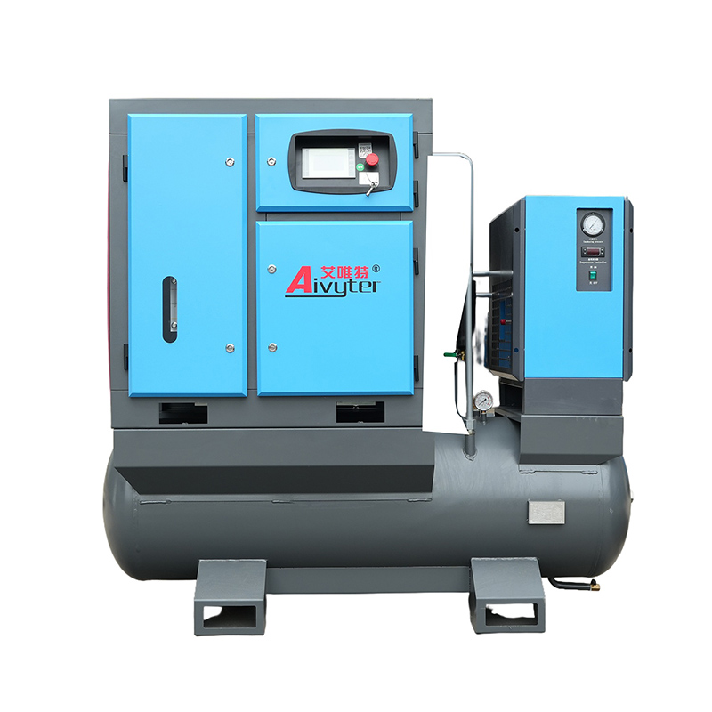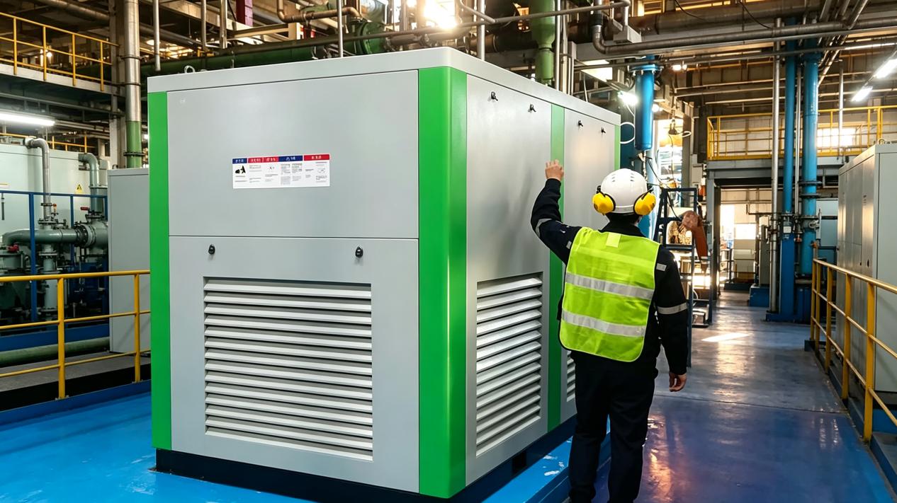
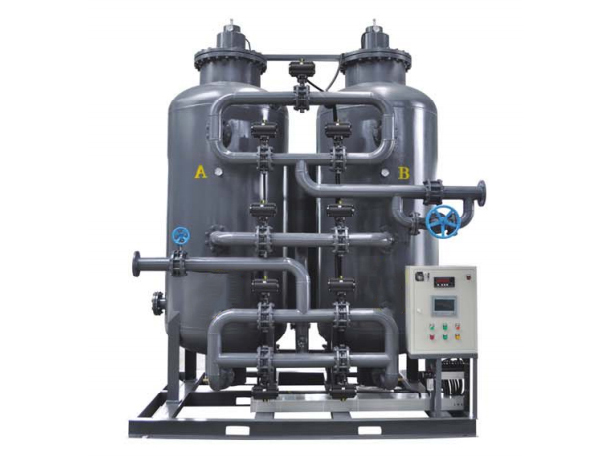
In high-capacity industrial, construction, and mining operations, compressed air functions as a primary energy vector. Rotary screw, centrifugal, and reciprocating compressors convert electrical or mechanical energy into pneumatic power. However, compressed air generation rarely matches real-time demand continuously. Rapid load changes, intermittent tool usage, and cyclic actuator demands create operational instability without adequate buffer capacity. Integrating a dedicated air compressor tank inside the pneumatic circuit solves these dynamic load imbalances, protecting rotary screws and downstream distribution pipework from severe pressure spikes.
Beyond acting as a pressure buffer, the receiver vessel serves functional roles in air treatment, moisture removal, and system load management. Proper pressure vessel selection directly influences electrical power consumption, mechanical maintenance schedules, and process reliability in continuous production plants.
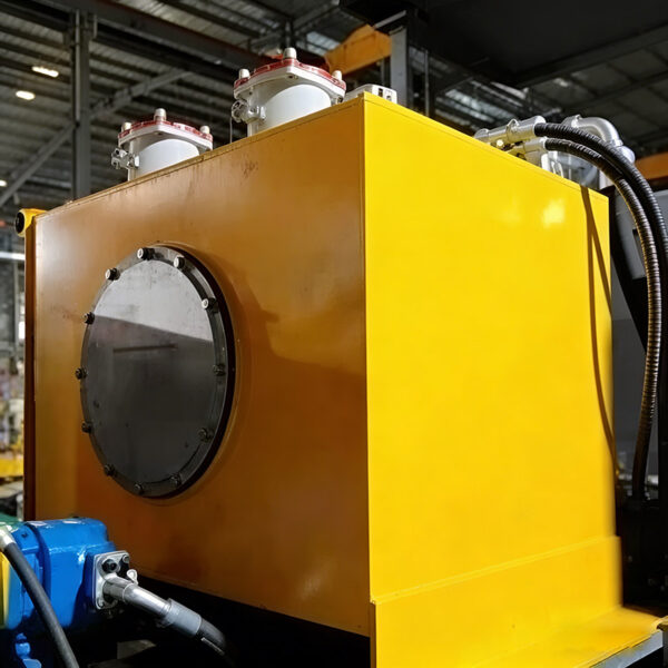
Fundamental Mechanics of Compressed Air Energy Storage
A compressed air distribution network without dedicated storage suffers from frequent pressure oscillations. Every time a high-volume pneumatic tool or heavy actuator engages, system pressure drops rapidly. The compressor controls attempt to compensate by unloading, loading, or modulating speed. This continuous cycling accelerates mechanical wear on inlet valves, contactors, and motor windings.
Buffer Capacity and Load Modulation
An intermediate pressure vessel acts as a surge damper between the air compressor and the point of use. By holding a reserve volume of compressed air under elevated pressure, the vessel absorbs sudden surges in demand without causing system-wide pressure decay. This dampening mechanism maintains stable line pressure across extensive piping networks, preventing low-pressure cutouts in sensitive automated equipment.
When plant air consumption falls below the displacement rating of the compressor, excess air flows directly into storage. The pressure inside the vessel increases until reaching the upper setpoint, allowing the compressor control system to unload cleanly or shut off. When demand rises, the air compressor tank releases stored energy into the main header, delaying the need to restart or reload the compressor package.
Thermal Cooling and Condensation Fallout
Air compression generates substantial heat. As ambient air compresses to operating pressures between 7 and 13 bar, its temperature rises sharply. Hot compressed air holds significant quantities of vaporized water. When air leaves an aftercooler, it remains warm and near 100% relative humidity.
As hot compressed air enters a large steel vessel, the velocity drops substantially. The expanded internal surface area allows heat dissipation to the ambient room air through radiation and natural convection. As the compressed air cools, water vapor condenses into liquid droplets. Gravity pulls this liquid condensate down to the bottom of the vessel, where zero-loss or automatic solenoid drain valves purge the accumulated water from the pneumatic system before it reaches air dryers or inline filters.
Engineering Sizing Calculations for Industrial Pneumatic Systems
Selecting an undersized vessel causes short-cycling, control instability, and excessive pressure drops. Conversely, an oversized vessel increases initial capital outlay and floor space requirements without offering proportional operational benefits. Accurate sizing depends on air displacement capacity, peak air demand, system pressure differential, and compressor control type.
A standard engineering formula determines minimum vessel volume based on volumetric flow rate and allowable pressure decay:
V = (7.48 × C × P1) / (P2 – P1) × t
Where:
- V = Tank storage volume in U.S. gallons
- C = Peak excess air demand over compressor output (CFM)
- P1 = Absolute inlet pressure (PSIA)
- P2 = Minimum allowable working pressure (PSIA)
- t = Duration of peak air demand event (minutes)
General baseline recommendations suggest maintaining between 3 and 10 gallons of storage capacity per CFM of compressor output, depending on application severity. Variable speed drive (VSD) compressors operating under steady load profiles generally require smaller buffer volumes. Fixed-speed screw compressors and reciprocating units require higher storage volumes to prevent excessive motor starts per hour.
Managing Duty Cycles and Motor Start Limits
Electric motors driving industrial air compressors carry strict limits regarding maximum permissible start cycles per hour. Large three-phase motors generate high heat loads during direct-on-line or star-delta starting sequences. Repeated starts within short windows degrade insulation, leading to premature motor failure.
By specifying adequate storage volume, the dwell time between loaded and unloaded states increases. This extended run time keeps the compressor operating within manufacturer-specified duty cycle limits while maintaining a narrow operating pressure band across the distribution plant.
Wet vs. Dry Air Receiver Configurations
System designers place pressure storage vessels in two primary configurations within an air treatment train: wet storage and dry storage. Each layout serves distinct process roles within heavy manufacturing environments.
Upstream Wet Storage Operations
A wet storage vessel sits directly between the compressor aftercooler and the air treatment system (refrigerated or desiccant dryers). Air enters the lower port of the vessel and exits through the upper port. Standard industrial setups utilizing Aivyter vessel designs leverage this layout to maximize mechanical moisture separation.
The primary advantage of wet storage lies in thermal load reduction. Because raw air enters the tank before entering downstream filtration units, liquid water and heavy oil aerosols knock out via gravitational settling. This reduces moisture loads entering desiccant or refrigerated air dryers, improving thermal efficiency and extending desiccant bed life. However, designers must account for pressure drop variations caused by saturated air entering downstream treatment equipment.
Downstream Dry Storage Benefits
A dry receiver tank sits downstream of air dryers and inline coalescing filters. The air entering this vessel is fully dried, cleaned, and dew-point controlled. Dry storage serves as a pure energy reservoir ready for immediate plant consumption.
During sudden demand events—such as baghouse pulse-jet cleaning, pneumatic conveying sequences, or large sandblasting operations—a dry air receiver prevents clean air shortages. Because the stored air is pre-treated, high discharge velocities will not surge through the air dryers, preventing moisture carryover caused by excessive face velocity through filter elements.
High-reliability facilities often deploy a dual-tank strategy: installing a wet vessel upstream to knock out bulk moisture and heavy condensate, accompanied by a dry air compressor tank downstream of the air treatment package to maintain clean header pressure.
Material Selection and ASME Pressure Vessel Compliance
Because compressed air stores significant elastic energy, storage vessels fall under strict international pressure vessel safety codes. Structural failure in a pressurized steel vessel carries severe plant safety consequences. Design specifications must match operational environments, pressure dynamics, and corrosive media exposure.
Carbon Steel vs. Stainless Steel Shell Construction
Carbon steel remains the dominant construction material for heavy-duty industrial storage vessels. High-tensile carbon steel offers high mechanical strength, structural durability, and cost performance. Internal surface coatings, such as baked epoxy or hot-dip galvanizing, prevent internal wall oxidation caused by acidic water condensate.
For specialized processing plants—such as chemical processing, offshore oil platforms, pharmaceuticals, and food production—304 or 316L stainless steel construction is standard. Stainless steel vessels eliminate rust flakes that could contaminate process lines and provide superior resistance to harsh chemical atmospheric conditions.
Regulatory Codes, Safety Relief Valves, and Inspection Protocols
Industrial storage units sold across global markets must comply with specific pressure codes, such as ASME Section VIII Division 1 in North America or PED 2014/68/EU in Europe. Compliance guarantees that shell plate thicknesses, head dishing geometry, joint efficiency factors, and welding quality satisfy design parameters.
Every certified air compressor tank must include mandatory safety appurtenances:
- ASME Safety Relief Valve: Spring-loaded pressure relief valve set to open at or below the Maximum Allowable Working Pressure (MAWP) of the vessel.
- Calibrated Pressure Gauge: Dial or digital pressure indicator providing direct visual verification of internal system pressure.
- Automatic Condensate Drain: Electronic zero-loss valve or heavy-duty timed solenoid valve ensuring reliable removal of liquid build-up.
- Inspection Ports: Threaded plugs or oval handhole/manway access covers enabling ultrasonic thickness testing and internal visual inspections.
Engineers specifying custom vessel shells, such as high-pressure units engineered by Aivyter, must verify that shell thickness accounts for corrosion allowances over a multi-decade operational lifespan.
Sector-Specific Applications in Mining, Construction, and Process Industries
Industrial pneumatic environments impose distinct operational loads on air storage systems. Understanding application demands ensures accurate equipment specification.
Deep Mining Underground Pneumatic Tooling
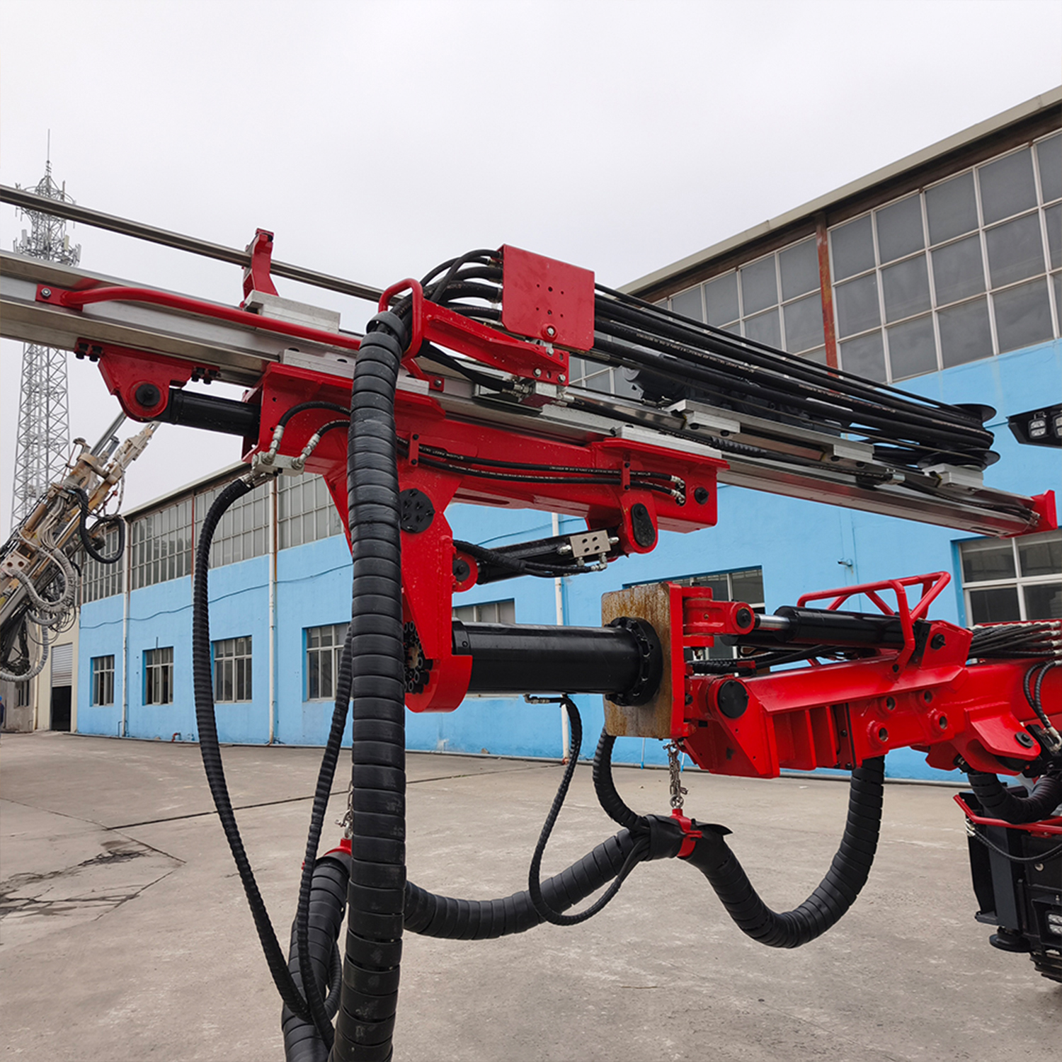
Underground mining operations utilize compressed air to power rock drills, continuous miners, face ventilation systems, and refuge chamber air networks. Piping runs in underground mines extend several kilometers down vertical shafts and horizontal drifts.
Friction losses along extensive pipe runs cause severe line pressure drops at distant working faces. Installing localized air receivers at mining junction points creates decentralized pressure reservoirs. These vessels ensure that rock drills operate at maximum strike energy without causing pressure drops across ventilation control valves and emergency life-support lines.
Heavy Civil Construction and Aggregate Handling
On construction sites and aggregate processing facilities, compressed air powers shotcrete sprayers, heavy demolition breakers, and pneumatic bin vibrators. Environmental dust, high ambient temperature swings, and outdoor exposure demand rugged equipment construction.
Engineers design skid-mounted portable air systems incorporating heavy-gage structural steel framing and weather-resistant external coatings. Tanks deployed on mobile compressor plants absorb severe vibration loads caused by diesel engine operation and rough terrain transport, requiring reinforced mounting pads and flexible hose isolation joints.
Continuous Process Manufacturing and Automation
In high-speed bottling, automotive manufacturing, and metal stamping plants, pneumatic cylinders execute thousands of rapid strokes per hour. Precision pick-and-place robotics demand absolute pressure stability to prevent dropped parts or sequence misfires.
In these facilities, stable air pressure translates directly into consistent cycle timing and product quality. Intermediate storage buffers absorb high-frequency pulsations generated by rapid solenoid valve firing, keeping supply headers balanced within tight tolerances.
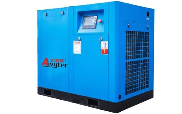
Installation Best Practices and Maintenance Schedules
Maximizing vessel service life and maintaining regulatory compliance requires strict adherence to installation guidelines and mechanical preventive maintenance schedules.
Installation Guidelines
Storage vessels should sit on level, reinforced concrete foundations capable of supporting the static wet weight of the tank during hydro-testing procedures. Floor anchors must secure the support legs without creating structural stress points on the vessel shell.
Isolate tank inlet and outlet connections using flexible stainless steel expansion joints. Direct rigid pipe connections transfer compressor vibration directly to the nozzle welds, leading to fatigue cracking over extended operating cycles. Provide adequate clearance around handholes, top heads, and drain valves to facilitate routine maintenance and ultrasonic wall thickness inspections.
Routine Maintenance Schedule
Establishing daily, monthly, and annual maintenance protocols prevents premature corrosion, drain blockages, and safety valve failures:
- Daily: Verify automatic condensate drain operation. Manually cycle manual drain bypasses to clear collected sludge and rust scale. Check pressure gauge readings against master compressor control panels.
- Monthly: Inspect safety pressure relief valves for external corrosion, scale build-up, or valve seat leakage. Test manual pull-ring mechanisms where safety protocols allow.
- Semi-Annually: Clean inlet strainers on automatic drain systems. Inspect exterior coatings for scratches, chips, or surface oxidation. Inspect flexible connections for signs of wear or mechanical fatigue.
- Annually: Perform internal vessel visual inspections through handholes or manways. Conduct ultrasonic thickness testing (UT) across lower shell sections and dish heads to monitor internal metal loss caused by acidic condensate accumulation.
Frequently Asked Questions
Q1: What is the main purpose of an air compressor tank in an industrial pneumatic system?
A1: An air compressor tank stores pressurized air, dampens pressure oscillations, minimizes rapid compressor loading and unloading cycles, and aids in cooling the air stream to knock out liquid water condensate before distribution.
Q2: How do I determine the right size receiver tank for my compressor plant?
A2: Tank sizing depends on total air output (CFM), peak airflow requirements, operational working pressure ranges, and compressor control mechanisms. A common engineering baseline ranges between 3 to 10 gallons of storage capacity per CFM of air output.
Q3: Should I place the pressure tank before or after the compressed air dryer?
A3: Installing the vessel upstream (wet storage) helps knock out bulk moisture and oil droplets before air enters the dryer. Placing the vessel downstream (dry storage) provides a clean air buffer that prevents velocity surges from overloading the air dryer during high demand spikes.
Q4: Why does liquid water accumulate inside my air storage vessel?
A4: Air compression increases air temperature and concentrates water vapor. As hot air enters the vessel, it expands and cools against the metallic walls, causing water vapor to condense into liquid. Installing dependable automatic drain valves ensures this water purges continuously.
Q5: How often do industrial pressure storage vessels require safety inspections?
A5: Operational visual checks should happen daily, while formal internal inspections and ultrasonic thickness testing typically occur every 1 to 3 years, depending on local jurisdictional pressure vessel codes and ASME regulations.
Engineered Air Storage Solutions for Enterprise Operations
Optimizing plant air capacity, reducing energy consumption, and protecting capital machinery requires precision-built air storage hardware designed for demanding industrial duty cycles. Standard off-the-shelf tanks often fail to deliver the mechanical reliability, internal coating durability, or regulatory compliance demanded by heavy processing plants, mining operations, and construction projects.
Aivyter engineers and builds heavy-duty pressure storage vessels tailored to modern pneumatic demands. Whether specifying custom ASME-certified carbon steel vessels, specialized stainless steel units for aggressive environments, or complete high-pressure plant integrations, receiving expert engineering guidance ensures long-term operational success.
Contact the technical engineering team at Aivyter today to submit your system specifications, request customized pressure vessel sizing calculations, and receive a detailed inquiry quote for your next infrastructure project.
about
Aivyter
We provides trusted air compressors and mining equipment, engineered for durability, efficiency, and demanding industrial applications.