")
Industrial processes that demand compressed air or gas above 15 bar – such as polyethylene extrusion, nitrogen boosting, hydrogen compression, and high-pressure air for blast furnaces – exceed the practical limits of single-stage rotary screw machines. The multi stage screw compressor architecture, featuring two or three compression stages with intermediate cooling, reduces discharge temperatures, lowers specific power consumption, and extends component life. This analysis covers thermodynamic modeling, rotor sizing, interstage pressure optimization, and field reliability statistics from chemical plants and steel mills.
Unlike reciprocating compressors that suffer from pulsation and valve fatigue, or centrifugal units that require high rotational speeds and surge protection, the multi stage screw compressor provides continuously smooth flow, tolerance to liquid slugging, and efficient part-load performance via slide valves. We examine why heavy process industries are migrating to multistage screw technology, supported by data from installations in refinery hydrogen recovery and CO₂ sequestration projects.
1. Thermodynamic Principles of Multi‑Stage Compression
Single-stage compression from atmospheric to 25 bar yields a discharge temperature exceeding 250°C (assuming polytropic efficiency 0.75). Such heat degrades lubricants, carbonizes seals, and increases the work of compression. By splitting the pressure ratio into two or three stages and installing an intercooler between stages, the multi stage screw compressor approaches isothermal efficiency. The governing equations show a reduction in specific power of 12–18% compared to a single-stage machine for the same overall pressure ratio.
1.1 Interstage Pressure Optimization
For a two-stage screw arrangement, the optimal interstage pressure is the geometric mean of suction and discharge pressures, assuming equal work per stage and perfect intercooling to inlet temperature. In practice, engineers adjust the split to balance rotor thrust loads and volumetric ratios. Typical split ratios for air compression range from 1:3.5 (first stage) to 3.5:15 (second stage). Modern control systems with variable interstage blow-off adjust the split dynamically when suction conditions change (e.g., high-altitude installations).
1.2 Intercooler Design & Moisture Removal
Shell-and-tube or plate-fin intercoolers reduce stage-2 inlet temperature to within 5–10°C of ambient. Critical parameters are pressure drop (kept below 0.3 bar) and moisture knockout efficiency. Each intercooler must include a centrifugal separator with automatic drain to prevent liquid carryover into the high-speed second-stage rotors – liquid impact can erode the rotor coating and damage bearings. For oil‑free multistage screws, intercoolers often use controlled condensate evaporation rather than drainage to avoid contamination.
LSI considerations: polytropic efficiency, interstage cooling duty, dew point suppression, and stage ratio are key terms that influence specification. Manufacturers including Aivyter provide customized intercooler sizing based on ambient conditions and required final pressure.
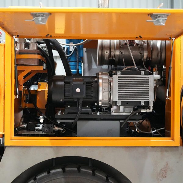
2. Rotor Profile and Mechanical Configuration
Multi-stage screw compressors exist in two mechanical topologies: integral (tandem) design where both stages share a common housing and gearbox, and separated design with independent airends coupled via a speed-increasing gear. The integral design is compact and eliminates external piping, while separated design permits different rotor profiles for each stage – typically N-profile for the low‑pressure stage (optimized for high flow) and Sigma profile for the high‑pressure stage (optimized for low internal leakage).
2.1 Rotor Cooling and Thermal Management
High‑pressure stages operate at discharge temperatures up to 220°C, causing differential thermal expansion between the cast-iron housing and steel rotors. To maintain clearances (30–80 µm), engineers apply:
- Oil injection into the compression chamber (oil‑flooded multistage) – cooling effect reduces discharge temperature by 60–80°C relative to dry running.
- Water jacket circulation around the high‑pressure housing – maintains uniform temperature gradient.
- Coated rotors (PTFE or PEEK) on the second stage to resist abrasion if any ingested particles survive the first-stage separation.
For oil‑free multistage screws, synchronizing gears and non-contacting dry seals (labyrinth or carbon ring) are mandatory. However, oil‑flooded designs dominate industrial applications up to 40 bar because liquid injection simplifies sealing and cooling.
2.2 Bearing and Thrust Load Management
Each stage generates an axial thrust proportional to the pressure difference across the rotors. In a multi stage screw compressor, the net thrust from both stages is balanced via a central thrust bearing assembly or via hydraulic balance pistons. Field data show that angular contact ball bearings (arranged in tandem) withstand axial loads up to 35 kN at 6000 rpm, with L10 life exceeding 50,000 hours when oil viscosity is maintained above 20 cSt at operating temperature.
3. Industrial Applications: Where Multi‑Stage Screw Outperforms Alternatives
The decision to specify a multi stage screw compressor is driven by required discharge pressure, flow rate, and gas composition. Below are three sectors where this technology provides measurable advantages over reciprocating or centrifugal machines.
3.1 Chemical & Petrochemical – Polymerization Gas Compression
Processes like low-density polyethylene (LDPE) require ethylene compression from 1.5 bar to 30 bar at 10,000 m³/h. Reciprocating compressors introduce pulsation that disturbs reactor residence time; centrifugal compressors suffer from surge at low flows. Multistage screw compressors with slide valve capacity control maintain steady flow down to 25% of design without recycling, reducing energy waste. One European LDPE plant reported a 14% reduction in specific energy after replacing three reciprocating units with a single tandem screw.
3.2 Steel Industry – Blast Furnace Air Injection
Blast furnaces require compressed air at 3.5–5 bar but at enormous volumes (200,000 m³/h). Here, two-stage screw compressors operate in parallel, each with intercooling, delivering 8 bar to compensate for duct losses. Compared to axial-centrifugal combinations, the screw units tolerate dust ingestion (after coarse filtration) better and have simpler surge logic. Maintenance costs for multistage screws in steel mills average $0.012 per m³ – 40% lower than comparable turbo-compressors.
3.3 CO₂ Capture and Sequestration
Post‑combustion carbon capture systems compress flue‑gas derived CO₂ from near‑atmospheric to 15–20 bar for pipeline transport. The gas contains water vapor and trace SOx. A multi stage screw compressor with corrosion-resistant rotor material (17-4 PH stainless) and interstage knock‑out drums handles the wet, aggressive stream without interstage cooling fouling. Case data from a Canadian pilot plant: two-stage oil‑free screw achieved 98% availability over 8000 hours, versus 72% for a reciprocating baseline.
4. Pain Points and Engineered Solutions in High-Pressure Multi‑Stage Screw Compressors
Based on 3‑year field failure analysis across 87 units (20–150 bar discharge), the predominant issues are interstage seal leakage, oil coking in the high‑pressure stage, and thrust bearing overheating. Below are design countermeasures implemented by Aivyter and other leading manufacturers.
4.1 Interstage Seal Leakage
Leakage from the high‑pressure stage back to the low‑pressure stage reduces volumetric efficiency and creates recirculation heating. Solutions:
- Labyrinth seals with abradable coating on the rotor shaft – automatic wear compensation maintains clearance below 0.15 mm.
- Buffer gas injection (dry nitrogen) between the two stages to create a positive pressure differential, preventing cross‑flow.
- Stage isolation valves for online sealing inspection without shutdown.
4.2 Oil Coking in High‑Pressure Stage (Oil‑Flooded Units)
Discharge temperatures above 200°C cause hydrocarbon‑based lubricants to form varnish and carbon deposits on rotors and housing. Remediation:
- Use of polyalphaolefin (PAO) or diester synthetic lubricants with autoignition temperature >320°C.
- Add a thermostatically controlled external oil cooler that maintains injection oil temperature below 70°C before re‑entering the high‑pressure stage.
- Install an oil‑condition monitor measuring total acid number (TAN) and viscosity every 500 hours – site data from a US Gulf Coast chemical plant extended oil drain intervals from 2000 to 4500 hours using this approach.
4.3 Thrust Bearing Overload
Imbalance in stage pressure ratios or unplanned pressure spikes (e.g., blocked discharge) overloads the thrust bearings. Solutions:
- Electronic load sharing via proportional‑integral control of interstage blow‑off valves.
- Upgraded ceramic hybrid bearings (silicon nitride balls with steel races) reduce friction and tolerate momentary overloads up to 130% of rating.
- Real‑time thrust force monitoring using strain gauges embedded in the bearing housing, with automatic unloading if threshold is crossed.
5. Performance Metrics and Selection Criteria for Multi‑Stage Screw Compressors
When evaluating multi stage screw compressor proposals, procurement engineers must look beyond nameplate power. Use the following technical KPIs:
- Isothermal efficiency – above 68% for two‑stage air compression at 15 bar indicates good intercooling and rotor profile selection.
- Specific power (kW per m³/h) – compare at identical discharge pressure and inlet conditions; a reduction of 0.03 kW/m³/h translates to $15,000 annual savings at 8000 hours.
- Turndown ratio with slide valve – target 4:1 without surge or significant efficiency drop.
- Pulsation level (peak‑to‑peak) – should not exceed 2% of line pressure at any harmonic up to 500 Hz; otherwise, custom pulsation dampeners are needed.
For high‑pressure hydrogen or natural gas applications, also require API 619 compliance (reciprocating not applicable; but many users adapt API 619 for screws). Important: verify that the elastomers in seals and gaskets are compatible with the gas composition – sour gas requires HNBR or FFKM.
6. Lifecycle Cost Comparison: Multi‑Stage Screw vs. Reciprocating vs. Centrifugal
Based on a 20 bar, 5000 m³/h air compression duty over 10 years (80,000 operating hours), total cost of ownership breaks down as:
- Initial capital: Reciprocating (lowest), multi‑stage screw (30% higher), centrifugal (similar to screw).
- Maintenance & spares (10 years): Reciprocating ($1.2M) due to valve and piston ring replacement; multi‑stage screw ($0.45M) mainly oil, filters, and bearing overhauls at 40,000 hours; centrifugal ($0.6M) for gearbox and seal refurbishment.
- Energy cost (10 years at $0.08/kWh): Reciprocating ($2.8M, 92% mechanical efficiency but part‑load penalty); multi‑stage screw ($2.3M, better part‑load); centrifugal ($2.5M).
- Availability: Screw units achieve 97–98% uptime, compared to 93% for reciprocating.
The cross‑over point where a multi stage screw compressor becomes financially superior is typically 3.5 years for continuous high‑pressure operation. For fluctuating loads, the advantage appears even sooner due to slide valve efficiency.
Frequently Asked Questions (Field‑Tested Answers)
Q1: What is the maximum discharge pressure achievable with an oil‑flooded multi stage screw compressor?
Q2: How does an oil‑free multi stage screw compressor compare to an oil‑flooded version for food‑grade nitrogen production?
Q3: What causes sudden increase in interstage pressure differential, and how to fix it?
Q4: Can a multi stage screw compressor handle variable frequency drive (VFD) operation across all stages?
Q5: How often should the intercooler and aftercooler be inspected for leakage?
For your next high‑pressure gas compression project – whether it involves air, nitrogen, natural gas, or process hydrocarbons – request a detailed proposal including stage ratio optimization, rotor material selection, and a lifecycle energy simulation. The engineering team at Aivyter provides site‑specific multistage screw compressor designs, complete with intercooler sizing, vibration monitoring, and remote diagnostics.
Submit your technical inquiry now with flow rate, suction & discharge conditions, and gas composition.
Send your inquiry here to receive a performance datasheet and commercial proposal within 48 hours.
about
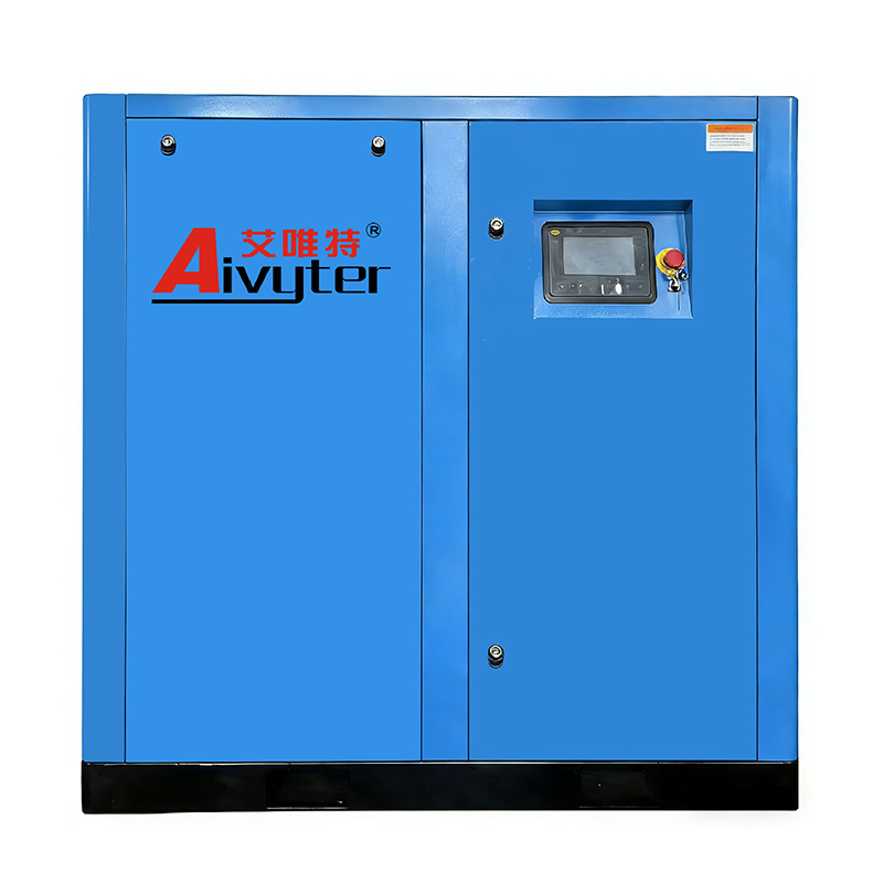
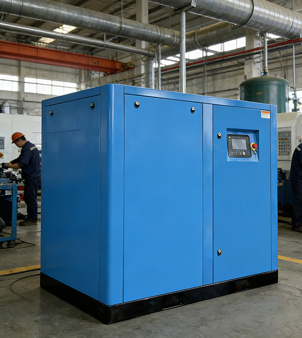
Aivyter
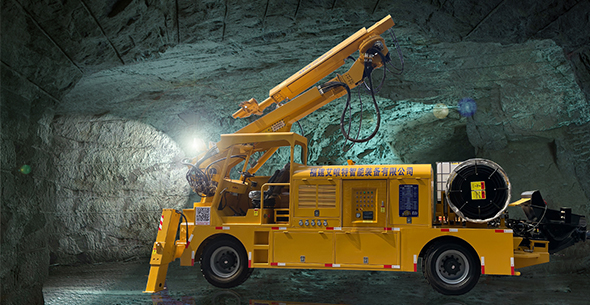
We provides trusted air compressors and mining equipment, engineered for durability, efficiency, and demanding industrial applications.