
Sub-surface operations in modern mining and civil infrastructure projects require highly specialized mechanical solutions to navigate variable geological strata. Excavating through hard rock formations, fault zones, and water-bearing ground demands systematic planning and precise execution. Within this domain, the implementation of advanced under ground drilling methodologies remains the primary means of creating blast holes, drainage conduits, and structural reinforcement paths. Equipment manufacturers like Aivyter design heavy machinery capable of operating in these confined, highly demanding environments, ensuring that excavation cycles progress systematically. Understanding the engineering principles behind these processes is fundamental to achieving high advancement rates and maintaining structural integrity throughout the life of the underground facility.
Primary Methodologies in Modern Sub-surface Excavation
The selection of a boring methodology depends on the physical properties of the rock mass, including uniaxial compressive strength (UCS), abrasiveness, and jointing patterns. Applying the incorrect mechanical force can lead to rapid tool wear or borehole instability, which slows down the excavation cycle.
Rotary Drilling Mechanics
Rotary systems utilize a continuous downward force combined with rotational torque to crush or shear the rock face. This method is highly effective in softer, sedimentary formations such as shale, sandstone, or soft limestone. Tricone bits or polycrystalline diamond compact (PDC) bits are typically employed to grind the rock into fine cuttings, which are then cleared from the borehole using water, air, or drilling mud. The continuous rotation ensures a smooth borehole wall, which is ideal for subsequent piping or casing installation.
Percussive and Rotary-Percussive Systems
In medium to extremely hard rock formations, such as granite, basalt, or quartzite, percussive force is necessary to fracture the geological matrix. Rotary-percussive systems combine high-frequency piston impacts with slow rotation to chip away rock. The piston strikes the shank adapter, transmitting a stress wave through the drill steel to the bit. This impact energy crushes the rock beneath the carbide buttons, while the rotational movement indexes the bit to fresh rock for the subsequent blow. This mechanical action is divided into top hammer and down-the-hole (DTH) configurations, each suited to specific hole depths and diameters.
Overcoming Structural and Geological Obstacles in Under Ground Drilling
Geotechnical exploration via under ground drilling provides precise stratigraphic columns, allowing engineers to map geological discontinuities before large-scale excavation begins. One of the most prominent obstacles is navigating high-stress zones where rockbursting or spalling is likely. When boring into highly stressed rock, the sudden relief of pressure can cause sudden fractures along the borehole wall, leading to jam-ups of the drill string.
Groundwater intrusion presents another significant challenge. Uncontrolled water inflow destabilizes the drilling face and washes away geological samples or blasting agents. To manage this hydrogeological variable, engineering teams utilize pre-excavation grouting. Specialized probe holes are bored ahead of the main tunnel face to detect water-bearing fractures. If high-pressure water is encountered, cementitious or chemical grouts are injected through the boreholes to seal the surrounding rock mass, creating a dry, stable zone for subsequent excavation phases. Rigs engineered by firms such as Aivyter to withstand high structural loads are vital during these high-pressure grouting preparation phases, where continuous torque and high feeding force are required to penetrate dense, water-logged strata.
Equipment Configuration and Mechanization
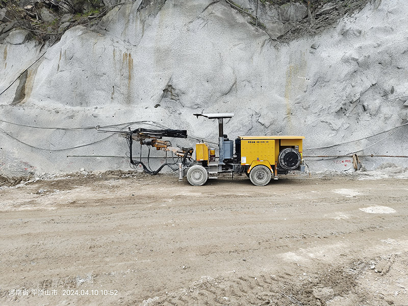
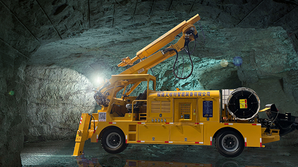
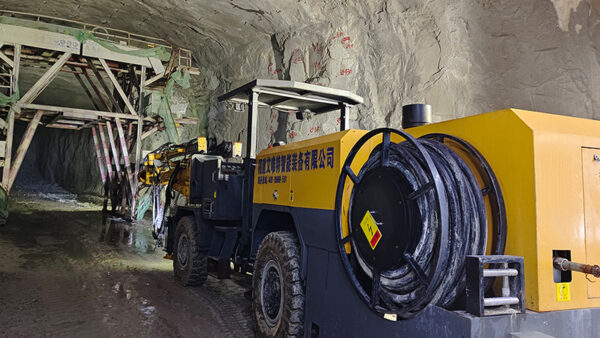
Modern sub-surface construction relies on mechanized under ground drilling platforms, specifically jumbo drill rigs, to perform face drilling, bolting, and cross-cutting. These machines are engineered to operate within restricted profiles while offering multi-directional boom movement to cover the entire tunnel face.
A typical jumbo rig configuration comprises several key sub-assemblies:
- Heavy Duty Booms: Hydraulic booms that provide precise positioning, parallel holding, and high-speed coverage of the face.
- Feed Rails: Structural steel or aluminum guides that support the rock drill (drifter) and maintain linear alignment during the feed cycle.
- Hydraulic Drifters: High-frequency percussion units that deliver the mechanical energy required to fracture hard rock formations.
- Carrier Chassis: Articulated, rubber-tired, or crawler-mounted vehicles designed for mobility in steep declines and narrow drives.
The hydraulic systems integrated into Aivyter rigs ensure consistent pressure distribution to both the rotation and percussion motors, reducing the likelihood of mechanical stalling in heterogeneous rock conditions. The systematic coordination of these components allows operators to maintain high penetration rates while reducing structural stress on the drill string.
Improving Precision and Deviation Control in Deep Boring
Controlling borehole alignment during under ground drilling is a complex engineering task. Deviation occurs when the drill string bends or deflects due to anisotropic rock characteristics, such as transitioning from hard granite to a soft clay seam, or when the feed force exceeds the buckling limit of the drill rod.
Borehole deviation leads to several operational inefficiencies, including uneven blast fragmentation, overbreak or underbreak of the tunnel profile, and ineffective rock bolt installations. To prevent these alignment errors, operators employ several strategies:
- Stiff Drill Strings: Using guide tubes or heavier-diameter rods immediately behind the bit to increase structural rigidity.
- Controlled Feed Force: Adjusting the feed pressure to match the rock hardness, preventing the drill string from flexing under excessive load.
- Instrumented Guidance Systems: Utilizing digital angle indicators and electronic feed alignment sensors that provide real-time positioning feedback to the operator.
Implementing these precision measures ensures that blast holes are parallel, which maximizes energy distribution during detonation and produces a clean, predictable tunnel profile.
Structural Support and Rock Bolting Integration
Boring holes for immediate ground support is an integral phase of the excavation cycle. Once a round is blasted and cleared, the newly exposed rock must be stabilized to prevent falls or structural collapse. This support is achieved by installing various types of rock bolts into pre-drilled holes, which bind the loose rock layers into a self-supporting arch.
Several dynamic bolting solutions are utilized depending on the geological conditions:
- Friction Bolts (Split Sets): Steel tubes slotted along their length that are driven into a slightly smaller borehole, relying on radial friction to hold the rock together.
- Resin-Anchored Bolts: Two-part resin capsules inserted into the hole before the bolt, which are mixed by the rotation of the bolt to form a high-strength chemical bond with the borehole wall.
- Cable Bolts: High-strength steel cables grouted into deep boreholes to secure large rock blocks deeper within the mountain massif.
Mechanized bolting rigs automate this process, allowing operators to drill, grout, and insert bolts from a safe distance, significantly reducing exposure to unsupported rock faces. This mechanical sequence must be performed quickly to prevent the rock mass from relaxing and losing its inherent strength.
Future Operational Standards in Sub-surface Projects
The sub-surface industry is transitioning toward digital integration and automated telemetry. Incorporating automated systems into under ground drilling protocols enables real-time data collection regarding penetration rates, percussion pressure, and rock hardness.
This data, often referred to as Measure-While-Drilling (MWD) logging, allows geotechnical engineers to analyze rock mass properties dynamically as the drill penetrates the face. Automated drilling profiles can adjust mechanical parameters in real time, preventing premature bit wear and reducing energy waste. This shift toward digital monitoring ensures that subsequent blasting and reinforcement steps are based on empirical geological data rather than visual estimation alone, leading to safer and more predictable project progression.
Consultation and Engineering Support
For specialized operations requiring customized mechanical solutions, consulting with engineering experts is the most reliable path to securing high-performance equipment. Detailed project specifications, including rock hardness metrics (UCS), tunnel cross-sections, and power source preferences, can be analyzed by the engineering department to configure appropriate machinery. Prospective partners are encouraged to submit an inquiry to discuss tailored configurations and geological feasibility assessments.
Frequently Asked Questions
Q1: What are the main causes of drill bit wear in hard rock excavation?
A1: Drill bit wear is primarily caused by abrasive friction, impact fatigue, and thermal stress. When drilling highly quartzitic formations, the abrasive minerals wear down the carbide buttons, requiring regular grinding to maintain penetration rates and prevent bit failure.
Q2: How does water flushing differ from air flushing in sub-surface drilling?
A2: Water flushing is typically used in underground operations to suppress dust, cool the drill bit, and clear cuttings from the hole. Air flushing is reserved for dry environments or specific geological formations where water might cause clay swelling or bore collapse, though it requires specialized dust collection systems to maintain air quality.
Q3: Why is parallel alignment of blast holes vital in tunneling?
A3: Parallel alignment ensures uniform burden and spacing along the length of the blast round. If holes deviate and converge, the blast energy is concentrated in one area, leaving uncut rock at the bottom of the face (boots) and causing poor rock fragmentation.
Q4: What is the purpose of a probe hole ahead of the tunnel face?
A4: A probe hole is a deep borehole drilled ahead of the active excavation face to detect geological anomalies, fault zones, high-pressure water aquifers, or gas pockets, allowing the engineering team to implement stabilization measures before exposing the tunnel to these elements.
Q5: How does a hydraulic drifter transfer energy to the rock?
A5: A hydraulic drifter contains a piston that is rapidly accelerated by high-pressure hydraulic fluid to strike a shank adapter. This strike creates a shockwave that travels through the drill steel to the bit, transferring kinetic energy directly to the rock face to fracture it, while a hydraulic motor provides rotation to index the bit buttons.
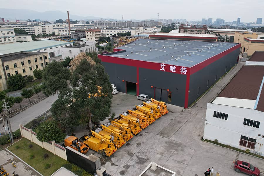
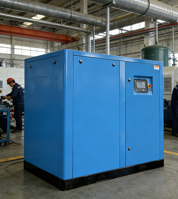
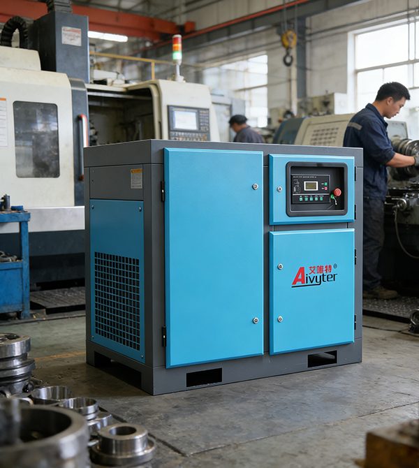
about
Aivyter
We provides trusted air compressors and mining equipment, engineered for durability, efficiency, and demanding industrial applications.